|
|
Post by Fletch on Jan 11, 2015 14:11:18 GMT -5
This is so cool! Looking forward to seeing how it all turns out.
|
|
|
|
Post by wardster on Jan 11, 2015 15:51:09 GMT -5
Thanks, Mr. Fletch! (Both for the compliment, and for the cool little resin kit!) I was going to wait and do another big update, showing several day's combined work ... but what the heck. Mini-updates count, too. 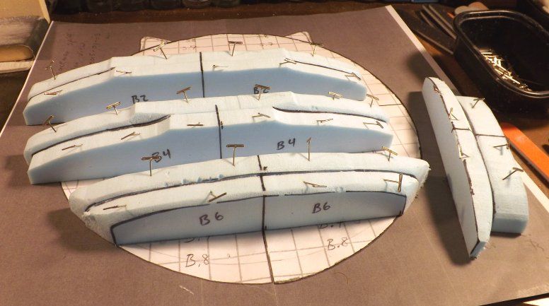 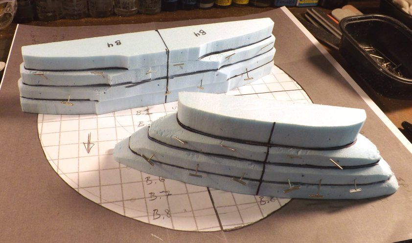 Basically, what I'm doing above is that I'm assembling the larger "kit". The slices of blue foam I had cut out, before, weren't glued together. They were just sitting there, stacked next to one another, in the latest pics. Now, they're getting glued together. The super-detailed, really-long version about all of the how's and why's of building big models out of that "foundation insulation" foam material would take me quite a while to type up ... so, instead, I'll preserve some bench time by just referring interested parties to an unrelated build thread, on a different set of web forums. I went into ridiculous detail on that, over here ... www.eagletransporter.com/forum/showthread.php?t=156062The way-shorter version of the explanation for the photos with the blue foam material is that you can buy it in huge sheets for about the same price as a new-release, injected plastic model kit; and with some time acquainting yourself with the idea of building things by cutting out "slices of bread" and then stacking them up, next to one another, to make a "loaf of bread" ... well, it's unusual; but it's cheap and (once you're used to it) it's pretty fast, too. The blue foam I'm using for this project came in a sheet one inch thick by four feet wide by eight feet long. One of my favorite local hardware stores sells sheets that thick for around $23 bucks or so, I think it was. They also have 1.5 inch thick sheets, and 2.0 inch thick sheets. Even with projects this big, a sheet lasts a LONG time! Anyway ... the first pic, above, shows that I usually tend to stick pairs of cut-out foam "slices" together, and let those harden up overnight or whatever ... and then, I stick two stuck-together pairs together; and let those harden up for most of a day or whatever. I find it's easier to keep things straight and "unbent" and what not, by doing things that way. If cuts made in prior stages aren't 100% at right angles, or flat, or straight enough, or whatever, you can adjust the imperfections with a sanding stick, before you glue things together. If you just trust that everything's square and such, without actually checking it, you can get some really weird sets of unintended curves or bends going. Doing things in pairs, and then pairs-of-pairs, lets a person be sure everything's going to "fit". More later, as work progresses. |
|
|
|
Post by Starryeyes on Jan 11, 2015 19:09:40 GMT -5
go Wardster go !! Looking good buddy... Following this one to the end!
|
|
|
|
Post by wardster on Jan 12, 2015 14:11:07 GMT -5
"Go Wardster go!!" just cracks me up. Thanks a bunch, Chuck! Here's another update. While the glue on other pairs of blue foam slices is hardening up, I'll post a few more in-progress pics. 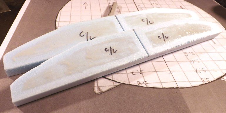 The photo above is here to show a couple of things. Mainly, it's here to show that I don't apply glue onto the slices, all the way to the outer edges. I put glue on both faces that will be touching one another, but I leave an "empty" border roughly a quarter of an inch wide, to maybe three-eights of an inch wide, around the edges and so forth. That's because the glue I'm using -- (I'll show a picture of the container, later) -- sort of foams up, and expands, as it cures ... and if I went all the way to the edges of the slices when I was spreading the glue, it would ooze out onto the surfaces I will have to sand down and smooth, later. I'm intentionally avoiding that, as best I can. Another thing I'm attempting to show, with that image, is that pair of foam slices is sort of special. Later on I'll want to be able to "find" the exact center of the cockpit area; and the bubbletop or glass dome above it. Why not define it early on? So, I carefully found that center (by placing one foam "centerline" piece on top of the "blueprints" of the craft's top view) and then marked marked that vertical line onto each carefully-positioned foam slice, with a Sharpie marker (and a small "L-shaped" 90-degree "square") ... and then, I scored a small line using a gentle stroke or two with a razor saw. Then, I gently used a rat tail file to define it better, on both pieces ... before I applied glue onto that pair of slices, and stuck them together. Giving me, once that was all done, a small "hole" that looks like it was "drilled" with a drill press or something, right where the left-to-right centerlines (which are shown on the "blueprints") cross over the front-to-back centerlines. Basically, in both cases what I did was to learn from past "well, I could'a done that better" experiences. By thinking ahead, I saved myself some later hassles. Switching subjects: 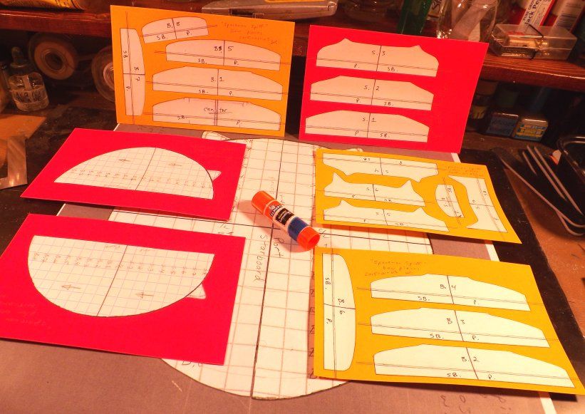 The shot above shows something I forgot to explain, earlier. Here's a close up on part of that, so you can see some of the details more clearly. 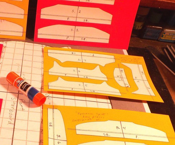 My wrists are bugging me, so I'll try to explain it briefly ... but what's seen in those shots above, are cut-outs of (enlarged, to 150%) computer printouts of scans of the 4-inch-by-6-inch index card tracings I had made ... of what that countour gauge told me the 2D shape of the craft was, along each pencil'ed "graph paper" line. (Note that although I had also made tracings of the front-to-back lines, I'm actually only using the side-to-side lines to make the bigger model. It can't hurt to be thorough, and document more than you actually need! And you may need it, later: you never know!) The 150% enlargements were each cut out, and glue-sticked onto bright posterboard. That posterboard having first been carefully measured, and then cut into rectangles which were sized exactly one half as big as the final 11-inch by 17-inch (photocopier) enlargements I would use as my final-final "actually cutting out foam slices" templates. Step-by-step, that process went something like this. I started with a bunch of individual contour tracings, drawn using a 0.5 mm mechanical pencil, on 4-by-6 index cards. I scanned those into my computer, without altering how large or small each drawing was. (I wanted 1:1 scale drawings, saved onto my computer, as-is.) Once they were saved at 1:1 scale, I printed them out on my inkjet printer, on normal paper ... with the printer's settings set to enlarge them to 150%. I made sure I had labels or names written on each printout, showing what "slice number" each drawing was -- ("bow" or "stern" and then a sequence number; or "C/L" for "centerline") -- and also labeled "port" and "starboard" -- (using the abbreviations "p." and "s.b.") -- and then, I used good scissors to cut them out. I made a few adjustments to overall symmetry, simply by folding each sheet in half, on the pre-marked centerline; and then holding each cut-out in front of a lamp; and trimming off any spots that didn't quite match up, from side-to-side. (There's more to the centerline's backstory ... but I'll cover that, later on. For now, just know that my drawing's / small models centerline markings were derived from tail fin's centers, cockpit measurements, and the like.) I played around (without glue) by "dry fitting" / positioning each slice's printout onto an "empty" piece of carefully-sized, colored posterboard rectangles. When I liked how the "puzzle pieces" looked, or were positioned, I used an everyday glue stick to attach the individual, enlarged-to-150% drawings. I took those six half-sized paste-ups to the local library, and asked them to enlarge these drawings to 200% percent; on 11-inch-by-17-inch paper. Giving me, at that point, somewhat-symmetrical (more so than the original kit's "halves," anyway) enlargements; sized at 300% of my starting point. You've already seen what came next: using those 3x enlargements of each "contour tracing" as templates, to cut out each individual "slice of bread". |
|
|
|
Post by wardster on Jan 16, 2015 16:10:13 GMT -5
Okay, so ... here's another pic-heavy update, showing recent work on (the upper half of) Mr. Spiff's spacecraft: 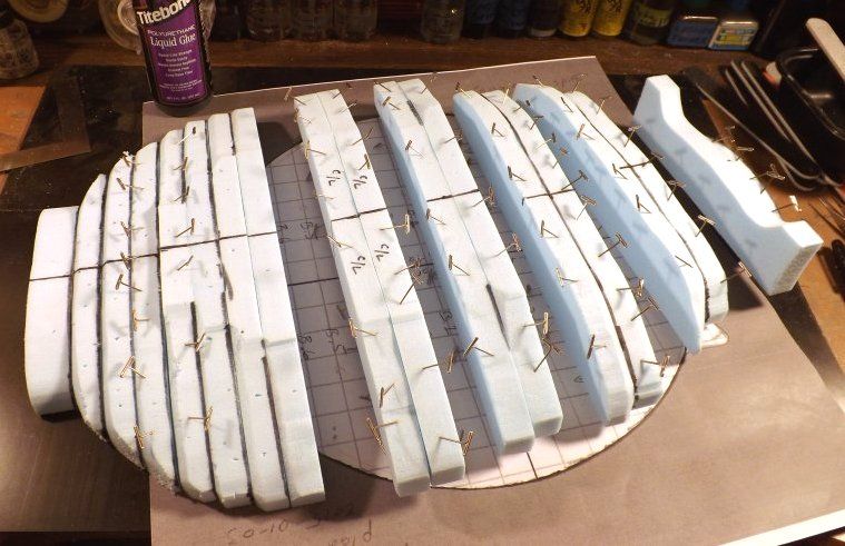 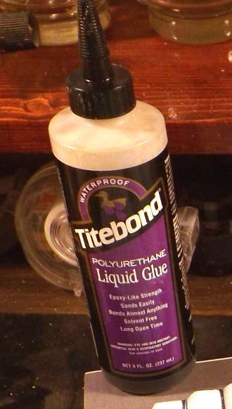 Pics above show the mostly-glued together foam slices; and the glue used to do it. 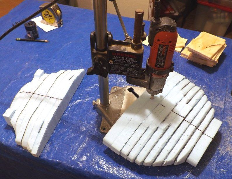 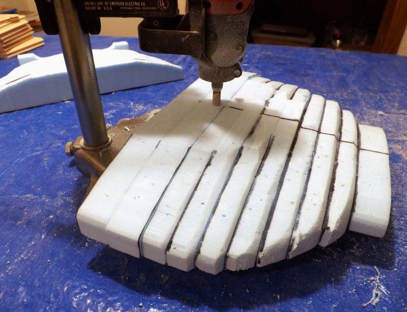 The two pics above are attempts to show my use of what I call the "Poor Man's Milling Machine" to flatten certain portions of the craft's upper surfaces. It's just a Dremel brand drill press, with the upper moto-tool-holding clamp's screw removed -- (so that a "foreign" brand of motor tool fits inside the device's clamp) -- that I'm temporarily pretending doesn't move up or down. To use it as a crude milling machine, for relatively simple "flattening chores," I load a flat bottomed cutting tool into the motor tool. Put that tool into the clamped area. Using the big built-in set screw which puts pressure on the device's strong vertical rod or tube, I adjust the cutting tool's height so that the bottom of the cutter is a specific (vertical) distance from the device's floor or table surface. I leave it there. Then it's just a simple matter of paying attention and keeping your fingers out of the cutter's way, as you slide whatever your're "flattening" back and forth, sideways, on the table's surface. I'd have to look up the part number of the Dremel-brand cutting (actually, more like grinding) bit I'm using -- but it's a course grinding bit, not a sharp-bladed "cutter" per se. Makes a bunch of dust, but doesn't do anything like pulling or tearing the surface. You get the idea of how it's done, I'm sure. Next up: I glued the front and back halves (quarters?) of the upper half of the saucer together; then, using the pre-marked center point indication, and a thick paper (posterboard) template that was six inches in diameter, I marked where the "hole" for the cockpit would need to go. (By tracing the circle template with a Sharpie.) 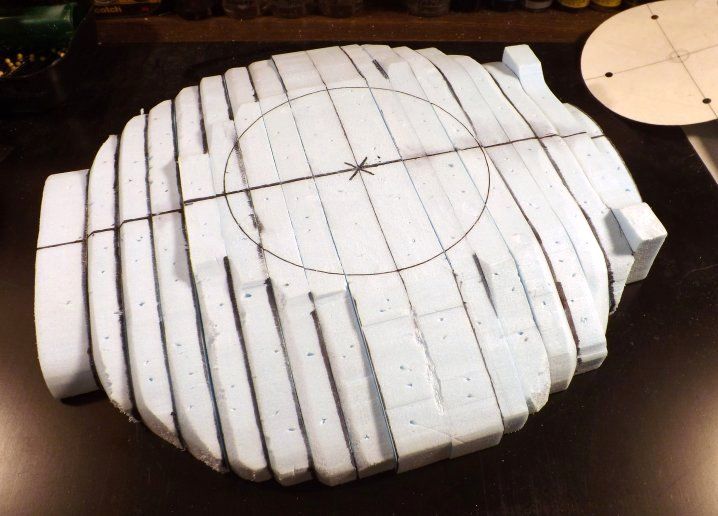 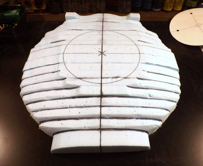 I flipped the whole piece over, and did basically the same thing on the bottom side -- this time, showing the craft's outer-most edges. 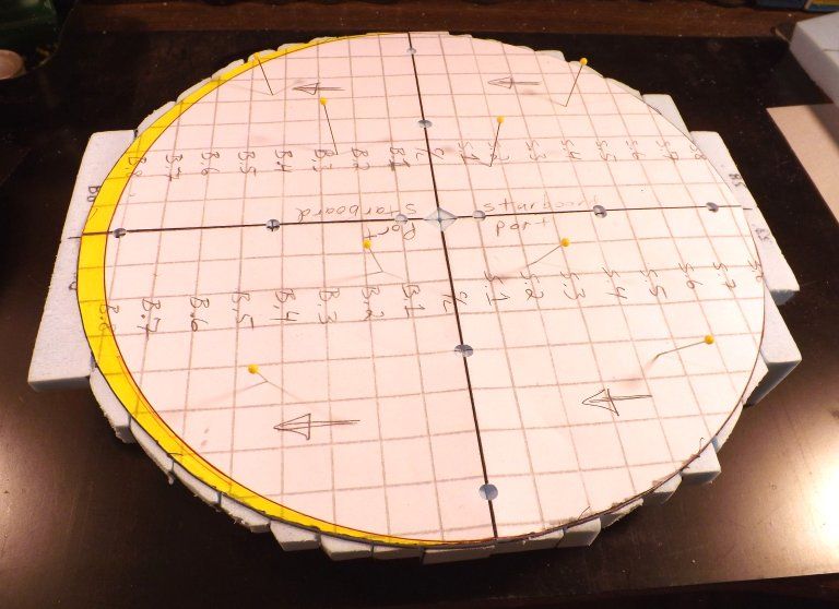 The template for that marking task is basically the enlarged "top view" blueprint drawing I've been using, in earlier shots ... with a few "clean-ups" and mods. I'll explain that work, a bit later. I want to press on with photos, for now. 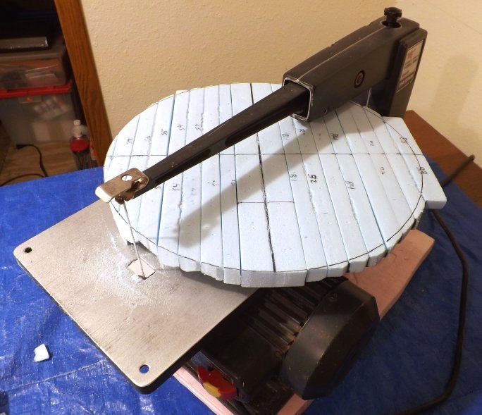 After tracing the outer edges of that template, I used a scroll saw to cut away any excess. Giving me a nice, clean "as seen from above" view, when that was done. 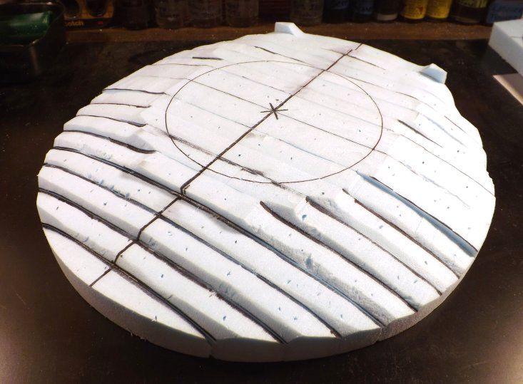 Then it was another scroll saw job, to cut out the cockpit's "hole". 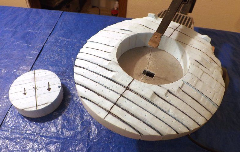 Next up will presumably be a bunch of clean-up work, mostly by hand and eye, to get rid of the ugly-looking "stair steps" along the upper surfaces. |
|
|
|
Post by wardster on Jan 20, 2015 14:35:43 GMT -5
Catching back up on image uploads, etc. -- 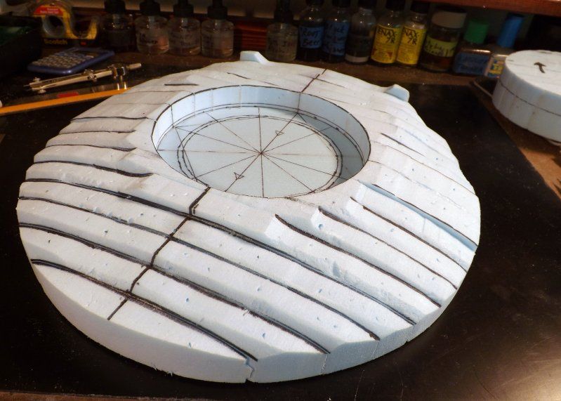 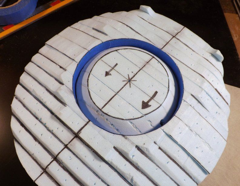 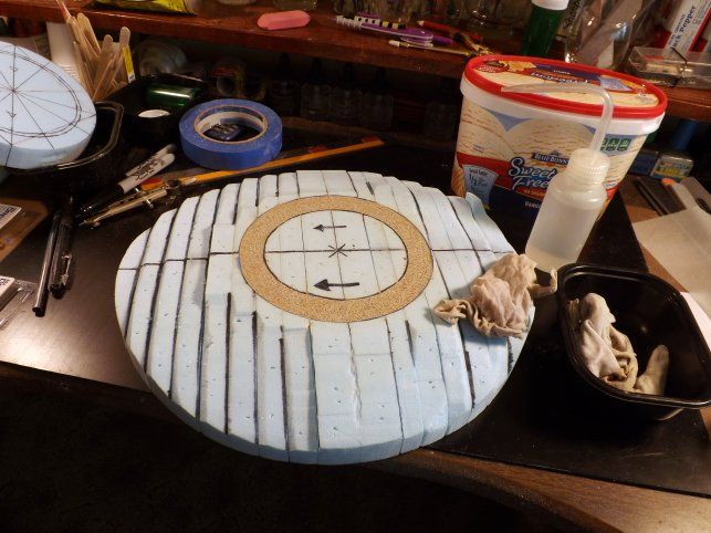 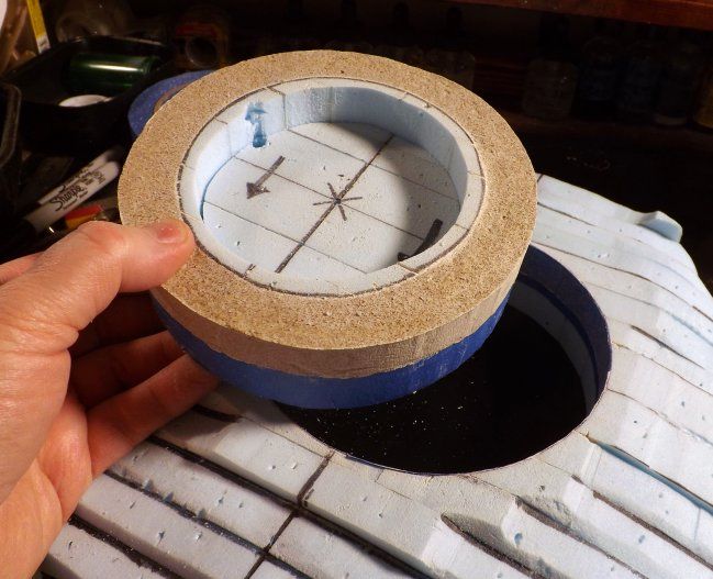 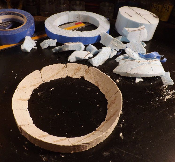 The idea behind what I'm doing, in the shots above, was to come up with a quick-and-dirty set of instrument panels. Not the final-final "kit part" -- just something I can plop in there, to compare sizes / proportions / angles / whatever, against what's seen in the original comic strips. In general, I've been changing a bunch of little things, here or there, and/or adjusting some things as I go -- (that is, when comparing the big model I'm making, against the small resin kit I used as a starting point). With things like contours, I'm just making different choices, here or there, based on that starting point. Contours and cross sections being an example of such "tweaks". But as far as the cockpit area goes: there, I'm basically starting over -- with a view towards making it look much more like the comic strips, if I can. To do that, I had to first work out how tall that circular set of panels was, on the big model; and how wide they were. I played with various "rings" drawn onto the piece of one-inch foam I had cut, and inserted -- with that new temp piece being there to act as moveable "floor" piece. (The top of a piston, in a sense.) The idea of that piece being that I could, by pushing it up or down within the saucer's body, figure out what looked about right, in terms of how "tall" those instrument panels should be, from top to bottom. I came up with a couple of different "not too bad" choices; and traced those rings onto the "cylinder walls". Once I had a rough "looks pretty good" panel depth figured out, I could then use those same "measurements" as temp numbers: marking off two different diameters, onto the piston's top. Think of it as figuring out the "bore" and "stroke" of the instrument-panels-to-be. Later, I'll make a much better-looking final instrument panel part ... but for now, this one will do what I needed. It's just sort of a place-holder, until I get other things figured out, as far as proportions, outlines, actual sizes of parts, and so on. Once I had the bore and stroke stuff figured out, I made sort of a "negative" mold, using that "piston top" -- cutting off or chamfering those upper edges -- and glopped a mixture of "plaster and vermiculite" into that cavity. I let it dry / harden for several hours, then gently pried the piston / panel pieces out of the cylinder ... and then cut and broke apart the piston piece (faster to do it that way, than to go looking around my already-messy shop areas, to try to find some sort of a mold release agent that wouldn't kill / eat the blue foam!) ... and put the cracked panel back together. In some of the easier-to-mask-off areas, I used blue painter's masking tape as a mold release agent. The waxy upper surface works fine, that way. Most of my choices, as to how to do that work, came about due to only having a few minutes, here or there, to get anything done on that day. Had I had more time, I'd have done things "better" -- but this is good enough for visual mock-up / sizing comparison purposes. |
|
|
|
Post by wardster on Jan 20, 2015 14:46:55 GMT -5
Here's where things start to look less like a mess, and more like pieces of a model:
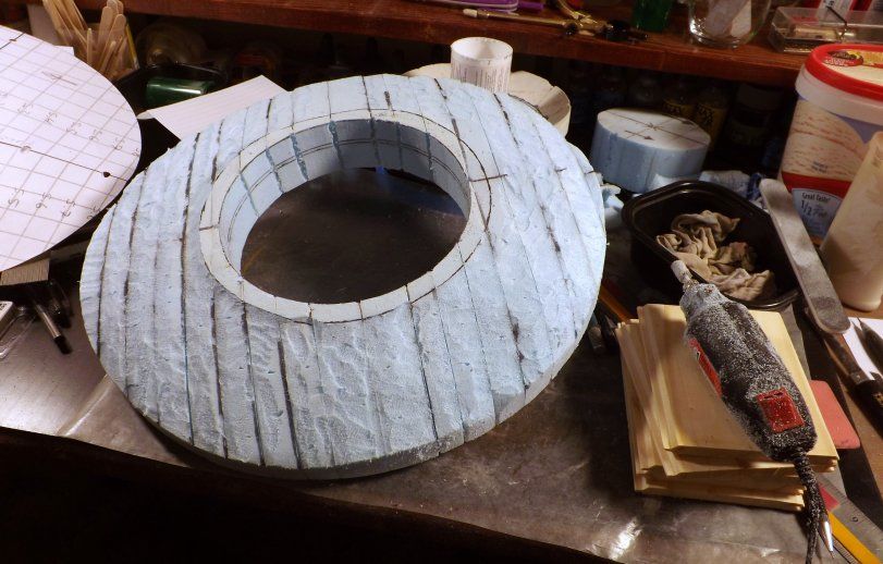
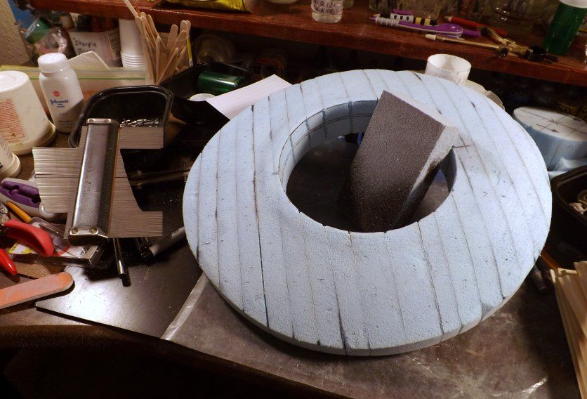
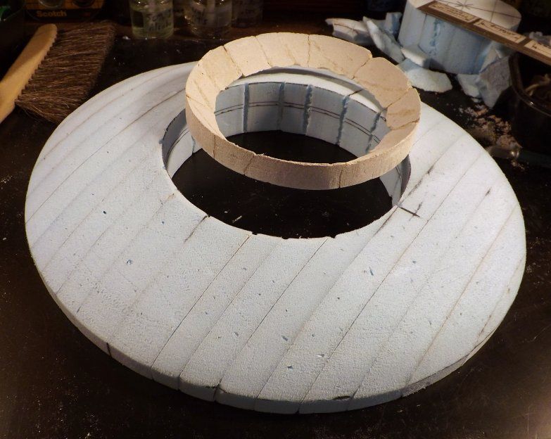
I had carefully and gently used the flat "top" part of that course Dremel-brand grinding bit, in a small (Harbor Freight brand, I think) moto-tool, to make most of the initial "getting rid of bumps and lumps" stages ... and then, a really course grit "sanding sponge" (from Ace Hardware, I think it was) to shape and smooth things, a bit more ... ending up with this:
I made such a dusty mess of my working areas, doing all that sanding and grinding work, that my first order of business during the following day was to go buy myself a new 2.5 gallon shop vac! I only had a little, half-worn-out DustBuster for that purpose, before this ... and the upgrade to an actual shop vac -- and a small, portable one at that -- was something that was way, way overdue!
Anyway, it's starting to look like something, finally. (Yay!)
|
|
|
|
Post by TooOld on Jan 20, 2015 18:10:19 GMT -5
And it's looking pretty cool too ! Very impressive .  |
|
|
|
Post by wardster on Jan 21, 2015 3:44:48 GMT -5
Thanks, man!  Time for some more pics! Here's the most recent work done -- 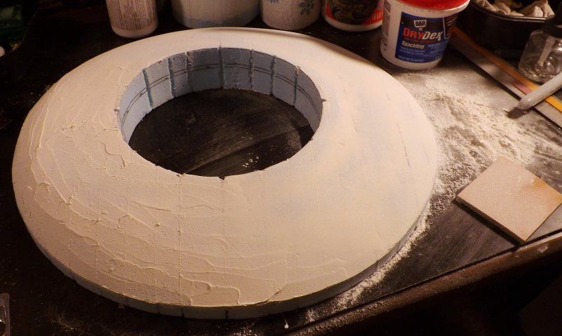 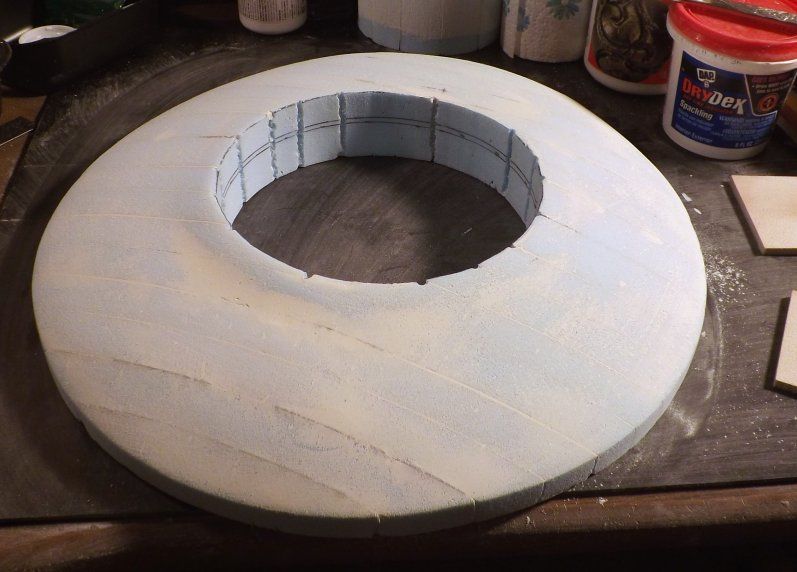 And here's some of the stuff I did it with -- 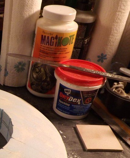 The "Magi Kote" stuff I'm just playing with, for now, on random pieces of scrap. Getting used to how it works, etc. The DryDex (by Dap) is the main stuff I'm actually using, here. That and some (3M-brand, I think) 180-grit sanding pad thingies. I just applied the DryDex, using an old butter knife; then let it sit and wait a while (till I had time to play with the model again; probably six or eight hours, in this case); then sanded it all smooth. I'll end up doing more of the putty-sand-repeat stuff, I'm sure -- (minor recontouring work needed in some places, etc.) -- but for "one pass" ... not too shabby! Here's one other thing I should probably show -- which may be helpful to some folks, if they try any of this for themselves: 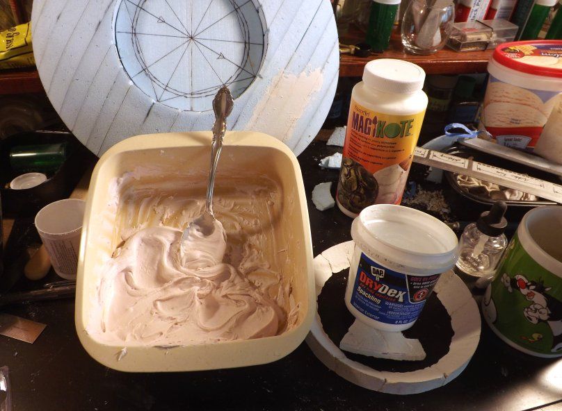 That's me getting the DryDex product to be more like icing; and less like half-dried, chalky mud. Not the product's fault: I've just had the same container around for a long time, and apparently didn't clean the lid's sealing area as well as I had thought I had, the last time I put it away. To make the product be smoother, and wetter, and more easily spread-able, I just dipped an old spoon in a container of water; then, I stirred the product for a while, with the slightly dampened spoon. I kept repeating getting that spoon wet, then stirring, till the product was well, "like icing". Doing things that way helps me to carefully control how much water gets added. Your mileage may vary, but for me, virtually always, if I just try to pour water in with the DryDex (or any spackle type product which is drying up on me, in the container) and then stir it in, it ends up being way too much added water. The mix ends up being a soupy mess! But the damp spoon trick is very control-able; and the results are always way better than any other methods I've ever tried. |
|
|
|
Post by ira on Jan 21, 2015 10:05:05 GMT -5
Great Progress Ward! 
|
|
|
|
Post by wardster on Jan 24, 2015 18:25:08 GMT -5
|
|
|
|
Post by wardster on Jan 24, 2015 18:35:46 GMT -5
|
|
|
|
Post by wardster on Jan 24, 2015 23:47:23 GMT -5
Here's two images of the "complete" model, so far. (That is, with most of the subassemblies present -- but with none of them in their final form, as yet.) This first photo shows a view of the front or bow -- so the craft's two sides (left and right, or port and starboard) should appear to be mostly alike. (Other than some photographic distortion I'm noticing -- and other than the stand-in for the cockpit's glass perhaps being a big off-center, it mostly seems "eyeball symmetrical" to me.) I'll double-check for symmetry, using tools, later on. 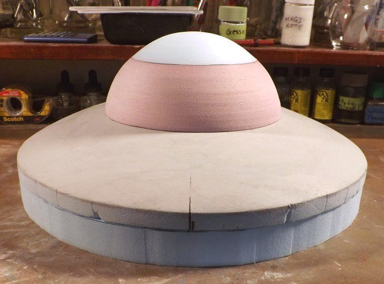 This next image is a side view -- with the forward section of the craft being seen on the left side of this photo; and the rear portion of the craft being shown on the right side of this photo. 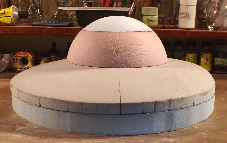 The blue dealie seen on the craft's bottom is just a random piece of one-inch thick blue foam, which is temporarily standing-in for the unshaped bottom portion of the craft. The idea at this point being that I'll likely stare at all of the parts, for a while; see how well they do or don't coordinate with one another -- and will also stare at the various images (of the "original thing") I've bookmarked in my collection of Calvin & Hobbes books. When I see something that needs fixing, I'll make up a "punch list" of items to address; and will deal with them, later on. |
|
|
|
Post by Fletch on Jan 25, 2015 12:13:13 GMT -5
Getting bigger and better every day!
|
|
|
|
Post by Starryeyes on Jan 28, 2015 19:47:55 GMT -5
Yeeeeooowww!!! you're scaring me to death and I'm not scared of anything !! .. Ha!!.. this is beautiful my friend ...
|
|

