|
|
Post by jcon on Feb 19, 2021 12:23:33 GMT -5
Coming together nicely, and I knew that engine right away having build a fundecker...
|
|
|
|
Post by wardster on Feb 19, 2021 22:19:00 GMT -5
Coming together nicely, and I knew that engine right away having build a fundecker... Thanks, man! Yeah, that engine is pretty much "iconic" ... at least in amongst we cartoon-loving vehicular modelers! That kit and the Swine Hunt, when I was a kid, were ones that I really loved. Still enjoy the creativity that "Big Deal" drew up for all of us! |
|
|
|
Post by jcon on Feb 20, 2021 0:22:43 GMT -5
Yeah they are fun for sure!!!
|
|
|
|
Post by wardster on Feb 21, 2021 5:08:27 GMT -5
Some initial, very-preliminary shaping ("contouring") work on the back end. Nowhere near done with this process, or the smoothing that also still needs to happen. But it's progress, so I figured I'd show it. This is of the same stage of the work: the lighting is just radically different in these two shots, since I rotated it 180 degrees, on the scanner's bed; so the light seems to be coming from a different direction. Until my local stores re-stock the camera batteries I want, pics like this will have to do.  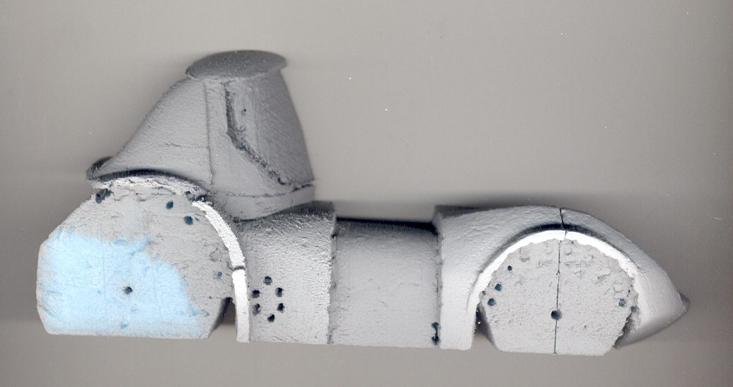 |
|
|
|
Post by jcon on Feb 21, 2021 11:28:35 GMT -5
Taking shape for sure!!!
|
|
|
|
Post by wardster on Feb 25, 2021 17:50:35 GMT -5
Had to go deal with Real Life Stuff for a few days, but I'm getting back into the swing of things now. One of the problems I mentally solved, since my last posting in this message thread, is probably best explained with a picture: 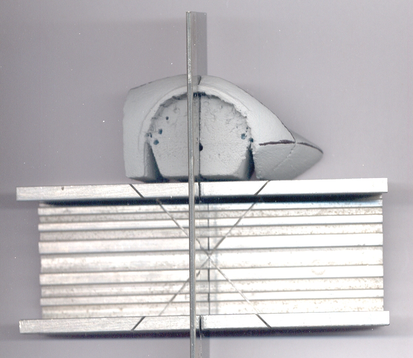 The metal X-acto brand "miter box" (a handy device, that probably lots of us here have) is not big enough for me to put the front end pieces where they are supposed to go (in between those parallel "walls") to "cut them into slices" ... so I had to, pretty literally, "think outside the box" to figure out how I would be able to cut up that "loaf of bread" into individual "slices of bread". As viewed from above, the foam front-end part was small enough to go into the box, between the two parallel metal walls. However, the part stuck way up, above the walls which are supposed to guide the saw; depending on how one looks at things, either the walls were too short, or the foam front-end part was way too tall (distance from the floor of the box) for the idea of a miter box to work. I came up with two solutions: one was to place the part to be scored (not fully cut, for now; but maybe later) outside of the box. That partially fixed the “walls too short” part of the problem. The second partial solution was that I raised the entire miter box, upwards, while keeping the foam pieces sitting on the table. That raised the wall’s height, relative to the part’s height (off the table, not “from the fictional ground to the top of the fenders.) Not shown is the three-eighths-inch tall chunk of balsa wood, to raise the entire miter box off of the table's surface. So in the end, I used the miter box somewhat as intended (using the pre-made ninety-degree slots to keep the saw blade aligned at right angles to the walls of the box, I mean) but I made the partial-depth-only initial cut, more or less as shown here. (It’s sitting crooked on the bed of my scanner, so apologies for the imperfect image.) That pair of tricks did what I wanted. I'll have to remember those ideas for later. I’m sure I’ll use it a lot, on this project, later on -- so it felt worth a mention. |
|
|
|
Post by wardster on Feb 25, 2021 19:21:27 GMT -5
Okay, here's the "end game" (so to speak) on why I wanted to make partial-depth cuts, in my foam "test model": 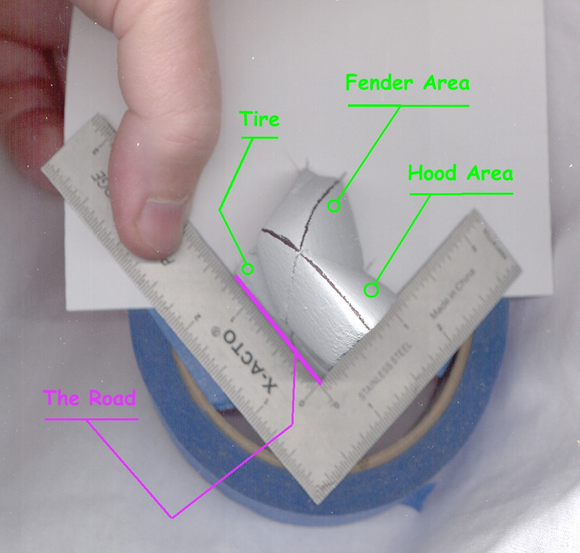 That probably makes no sense, without more of an explanation, so here goes. I'm not sure I can explain this super-well? A lot of what I do on "test models" is aimed at a stack of 2D cross section drawings. To get those drawings, I can either totally destroy (or badly damage) my one-and-only "test model" ... or I can "damage them a little bit" while still "mostly keeping them intact". Back when I was in the Air Force, I'd hear terms like "non-destructive testing" (on things like the sheet metal used on an aircraft's fuselage or flying surfaces / wings, etc.) or "destructive testing". I'm trying to pick a point on a line, that's more towards "non-destructive" than "yeah, absolutely, it's destroyed". What's going on in this image is that I gently shoved as much of a three-inch-by-five-inch index card, into the slice or crack I had made, with the thin-bladed X-acto brand razor saw, in the prior update. (See posting, immediately above this one.) That gives me about half of the information I need. If I cut the slice completely off, I could simply trace it, all, directly -- including the reference marks that the small (X-acto brand, again!) "L-shaped" square is telling me. Because I'm holding this all in my aging fingers, and I'm not exactly as manually adept as, say, a concert pianist or a violin player, I'm cheating a bit, by using a roll of tape from behind, so that the small square has three points of contact with the "donut shape" of the roll of tape. Otherwise, things are flopping all over the place, and I can't get accurate tracings. Visually, I only need the paper (which is stuck into the test model, at the point shown in the prior posting) and the ruler, but in practical terms, I needed a support device that would sandwich the square over the paper, or the paper under the square. Tape was nearby, so it got used. The piece of paper is shoved (gently) into the saw cut, so that I can trace around the body's outline, as it crosses the car, from the (in this particular case or instance) visible front axle's centerline (as seen from above the car) to the other axle, which is "invisible" since I didn't build that half of the vehicle. I just push the paper into the crack, and trace it with a mechanical pencil, with a nice / sharp / small-diameter pencil's lead, for maximum precision. But experience with many test models has shown me that a 2D tracing of those surfaces, alone, without any reference to where the road surface (or in this case, actually, the bottom plane of the vehicle) is located, is pretty much worthless. That also is true for not having any visual, trace-able indication of where the vertical center line of the vehicle is: the line that is exactly halfway between the "driver's side" and the "passenger side" of this vehicle. The longer leg of the square, when traced, shows me where the bottom plane of the vehicle (which I accidentally mislabeled as "road" -- sorry!) is, in reference to the vehicle's centerline (which in this case is the square's shorter leg) ... and the tracing of the part, itself, gives me all the cross sectional data that I need, at that one point on the test model. I plan to repeat these steps, over and over, at various points along the vehicle (test model). Probably at three-eights-of-an-inch points, from the vehicle's nose or tip of the front end, all the way to the back end. Which is the "slice thickness" that I'll probably use for the "real model," when I've measured all that I want to, or need to, on the "test model". What's the benefit to doing all of this? Down the road (pardon the bad pun) you're assured of symmetry from side to side, when you build the final model. As long as you take care to mark off each flat "slice" carefully, you can simply treat each "slice of bread" as being equal on both sides: just flip the 2D template over, to mark the passenger's side, if you've already marked off the driver's side ... or vice-versa. Yes, it's a lot of work to end up with all of the 2D cross section data ... which is in turn based on a "test model" that you (or at least, "me") will likely basically ignore, once you have the 2D data that you want. But if you want to double the model's size, just use "slices" twice as thick, and scale the 2D cross section drawings up to 200% of what you started with. Or any other number you want to use: so long as you scale the slice thickness up or down, by the same amount that the drawings change.) Hopefully, that makes some sense? I know this stuff was mind-melting, for me, at first, when I was studying some of what ship modelers do, so I could mis-apply it to things like sci-fi models, and/or cartoon vehicles!) ... but eventually, with more steps shown, it may make more sense? |
|
|
|
Post by wardster on Feb 25, 2021 20:04:56 GMT -5
Here's a bit more visual data -- one actual cross section drawing, of that one "station" along the length of the vehicle: 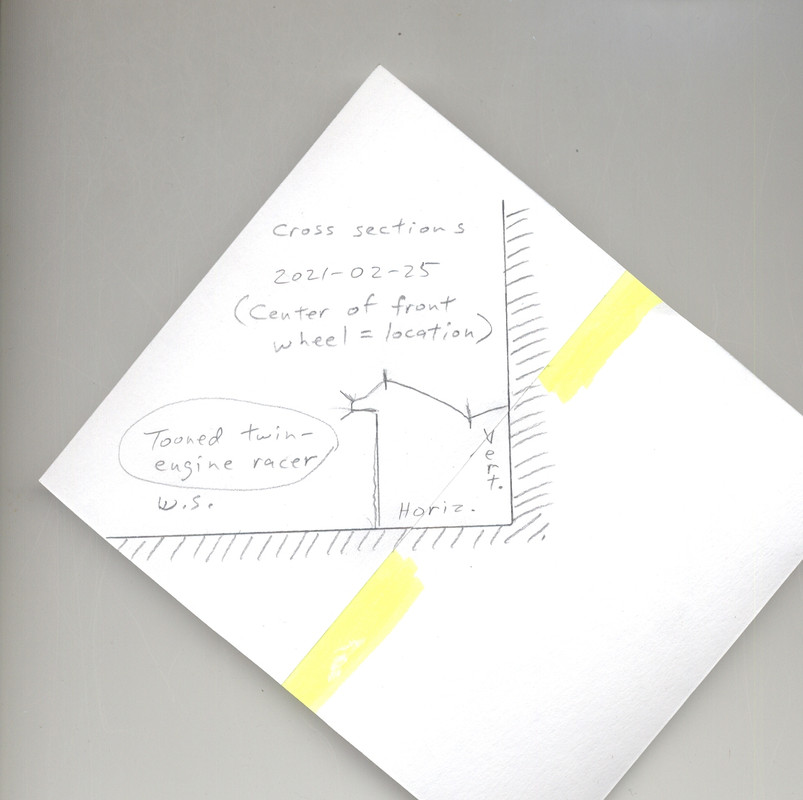 To "fill in some missing data," as it were, I had to tape on a second index card, where the (five-inch-long) factory edge of the first three-inch-by-five-inch index card couldn't be inserted all the way into the car. I marked (with a yellow highlighter) the second card's edge, where it butts up against the first one; thus showing, or attempting to, what would be missing if I didn't tape that other card onto the first one. But this is easy work to do: just use a ruler or a square to continue the fragments of lines, traced outside the body's edges; thus re-creating the horizontal line (the vehicle's bottom plane, as shown here) and the vertical centerline. Normally, I'd mark some kind of a "station number" on each drawing, so I don't lose track of which one is which. I haven't yet figured out what number this one would be, so, for now I'm just putting a date and some other general info, on this scan. |
|
|
|
Post by jcon on Feb 25, 2021 20:07:44 GMT -5
Very cool!!!
|
|
|
|
Post by wardster on Feb 25, 2021 21:01:21 GMT -5
Thanks, Joe! Much appreciated! As seen below, the back half is doing a perma-wheelie ... as all good race toons should, I guess? Heehee. (Unless they're not moving, and then they better be looking either really cute, or somewhat cute and rather bad a**?) 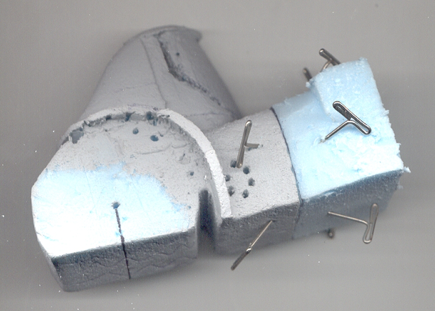 I'm actually showing that to show my "gluing stuff back together" steps. Not shown is the (Titebond brand) polyurethane glue. Bonding area isn't the whole surface of what I'm attaching / sticking together. That stuff expands quite a bit, even if you don't add any water to it, so, when I'm sticking foam blobs together, I only put glue on say, the inner half-inch of an inch-wide surface, so that it doesn't stick out of the seams. The glue is WAY harder than the foam is, which makes sanding it a major pain (without totally obliterating the foam) hence the extra care. The many "T-pins" shown here are the way I make sure that while it's drying, nothing shifts or slides around. I use these pins for several reasons, one is that the head makes it easier to get them back out! I often have to go right through the glue, itself, with the pins, so a bit of added leverage, to rotate the pin around its axis, helps. |
|
|
|
Post by jffj on Feb 25, 2021 21:30:55 GMT -5
Thanks, Joe! Much appreciated! As seen below, the back half is doing a perma-wheelie ... as all good race toons should, I guess? Heehee. (Unless they're not moving, and then they better be looking either really cute, or somewhat cute and rather bad a**?)  I'm actually showing that to show my "gluing stuff back together" steps. Not shown is the (Titebond brand) polyurethane glue. Bonding area isn't the whole surface of what I'm attaching / sticking together. That stuff expands quite a bit, even if you don't add any water to it, so, when I'm sticking foam blobs together, I only put glue on say, the inner half-inch of an inch-wide surface, so that it doesn't stick out of the seams. The glue is WAY harder than the foam is, which makes sanding it a major pain (without totally obliterating the foam) hence the extra care. The many "T-pins" shown here are the way I make sure that while it's drying, nothing shifts or slides around. I use these pins for several reasons, one is that the head makes it easier to get them back out! I often have to go right through the glue, itself, with the pins, so a bit of added leverage, to rotate the pin around its axis, helps. Nice WIP work Wardster! I use the TiteBond original wood glue and love that it is sandable. You're so right about it being harder than the foam, and I mostly use balsa wood to make my pieces, and while not quite as hard as the dried TiteBond, it's hard enough for my sanding purposes. I then coat the balsa with 2 coats (at least) of the TiteBond, lightly sanding between coats, which yields an almost plastic smooth surface. |
|
|
|
Post by jffj on Feb 25, 2021 21:37:06 GMT -5
I really like the idea, technique, of making cuts- slices- in which you slide the index card to trace the profile. Stored away in my brain for future use. Thanks Wardster 🤗
|
|
|
|
Post by wardster on Feb 25, 2021 23:43:37 GMT -5
I really like the idea, technique, of making cuts- slices- in which you slide the index card to trace the profile. Stored away in my brain for future use. Thanks Wardster 🤗 Thanks, jffj! Hearing that kind of thing is probably the best compliment, ever! We all learn from each other! As far as the term "slices" goes ... Normally, I really am using a technique that is a lot closer to being "slices of bread" ... in other words, the "slices" aren't so much a cut, as shown here, but a solid piece. Working with that method is like taking one slice of bread out of a loaf of bread, temporarily, to work on the outer edges a bit, and then you just plop it back into the "loaf" and keep going. Hence keeping one side flat, all of the time ... or in this case, two of the four (sides). As you already know, from your having laid things over the blueprints you made up, it's so much easier, at times, keeping everything "straight, plumb, and level" by plopping parts over a set of blueprints or working drawings. I actually put some clear shelf paper lamination over my main drawing, to do just that, with the next steps. I'm going to be using some combination of my favorite plaster-like material (Dap brand Presto Patch) along with some vermiculite (which I ground down, really fine, using a small portable coffee grinder) and I'm experimenting, a bit, here and there, with mixing some talc in with the other two ingredients. And treating it like a mini version of auto body filler, aka, "Bondo". I might experiment with my favorite epoxy modeling putty (Magic Sculpt) to see if it eats or likes foam. A lot of what I'm doing, right now, boils down to "get it done, anyway, even if you don't have the correct stuff -- that is, the stuff you usually use". I'm out of my comfort zone, somewhat, and improvising. That bit you mentioned, about shoving the paper into the foam model: I'm not sure I ever used that, before. I think I was tempted to, with past models, but didn't, for the simple reason that I didn't have to. I was usually working with "many loose slices of bread," aligned with one another just by having one thin flat side (to sit on the working drawings, upright) and to keep it all aligned in another axis, a horizontal line, usually located at the center (vertically speaking) and traveling, longitudinally, from front to back. With this one, I'm using the "bottom plane" of the model as that "align each slice, on the vertical axis" line ... if that makes any sense? I'm not doing what I usually do, here -- at least not so far -- for a variety of reasons. One reason is: these foam parts, in terms of raw size, at least as compared to several models I did in the past, seem like "half of a sub-assembly" or something, instead of the actual model pieces. I don't know if that makes sense or not? Even though this foam test-model is probably three times the size of the original Hot Wheels vehicle I'm sort of "up-scaling" in size, man, there are moments where it still seems like it's half the size I'm used to working on! I guess the plastic model airplane guys might compare it to working in 1/72 scale, instead of 1/48 scale? I keep being tempted to get to a certain point with this half-hull model, to where I sort-of-kind-of trust the sectional drawings, and then, double it up in size, and do that trick I mentioned before, of alternating pink foam with blue foam. I'm not saying I'm definitely going to make that larger model, but I might. Depends on how much I trust the 2D drawings, I guess? And how excited I am at "nailing" the nuances of the "flow"? Right now, I am still "trying to get into the ballpark". The back end I'm about to switch to a coating, over the foam, and sort of winging it, in a sense -- following more of a sculpting-style of process, than the semi-engineering processes I prefer. Another reason I'm deviating from my norm is that I don't, at present, have access to a working printer! I let my aging inkjet printer's last cartridge die out on me, without spending much time refilling it / getting it working, because the local library got a really sweet, leased, color laser printer. I got used to that machine. Dependent on it, in a way. Then ... everything closed! Normally, too, I'm using something like big fat hard solid MDF sheets, that I'm sanding the outer edges down, with a one-inch wide belt sander, to get everything as exact as possible. But freezing out in the unheated garage doesn't sound pleasant, and I don't want to be mixing up auto-body materials, indoors, with my dog around. I don't mind stinking myself out of the house, putting the final "icing" over some MDF "slices of bread, but I would feel sorry for my dog ... so, I switched over to lightweight foam, and I'm treating as much of my usual-to-me methodology as I can, as a "transferable skill". And I'm taking LOTS of notes on all the new-to-me stuff I'm doing, and posting them here ... 'cause in six months, if I don't, I'd likely forget half!? Anyway ... thanks again, for liking that technique so much! |
|
|
|
Post by wardster on Feb 25, 2021 23:49:50 GMT -5
Nice WIP work Wardster! I use the TiteBond original wood glue and love that it is sandable. You're so right about it being harder than the foam, and I mostly use balsa wood to make my pieces, and while not quite as hard as the dried TiteBond, it's hard enough for my sanding purposes. I then coat the balsa with 2 coats (at least) of the TiteBond, lightly sanding between coats, which yields an almost plastic smooth surface. Thanks again, sir! I'm curious: have you ever tried to use MinWax's liquid, brush-on "wood hardener" on Balsa Wood? I've not tried it on Balsa wood, yet, but it works really well on a lot of other mostly-porous or fairly-wood-like materials. It's sometimes a bit corrosive, and I'm sure it would EAT foam like a monster in a 1960's movie eating, well, whatever it wants to I guess ... but it has been used by me, experiment-wise, with Balsa Foam, to good effect. (And various things like actual wood, like pine or harder. I just didn't try it on actual Balsa Wood, yet.) And it does, if memory serves, a pretty good job of soaking into applied-and-shaped batches of "plaster and vermiculite" ... The gray stuff that I applied to the blue foam, earlier, I don't think (?) I mentioned, in any detail. I'll look up what I use, and try to post it, in the next few steps. I had worked out a pretty specific set of products, with each being used for a given task. A lot of things will just flat out EAT this foam, so I'm mostly using stuff that's water-soluble. I imagine it'd work with Balsa wood, too. I have some scrap pieces I can practice with, to see. "MagiKote" is one product I use, with the foams. I just added some black acrylic (tube-based, not that it probably matters?) paint into it, to turn it from a white color to a "primer gray" variant. |
|
|
|
Post by wardster on Feb 26, 2021 0:50:27 GMT -5
Okay ... I'll interrupt myself, to throw in an image of a completely unrelated model, since the image demonstrates one of the techniques I was talking about, earlier, a time or two, in the text of this Work In Progress thread ... 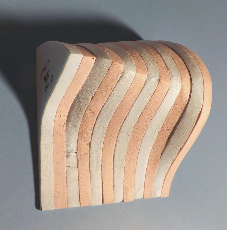 This is, as I say, not an image of anything to do with this model. It's actually a historical model boat that I was "figuring out the shape of" the hull of, to a finer and more nuanced degree than any "lines drawings" we amateur researchers had come up with. Given the obscurity of the subject matter (an American Civil War vessel, called the C.S.S. Manassas) and not wanting to bring politics up, in any way at all, I'll leave it there, text-wise, as far as "what's this a picture of". The point of me including this image at all is that I knew that I was dealing with an incredibly complex shape, with that project. The area I was really struggling with was not well-defined in the drawings I had: too few "stations" were spelled out, in the area near the cut out (for lack of a better way to describe it) for the steam engine's twin propellers. It had two "S-shapes" going on, at the same time: one vertically, and one horizontally. And when I was cutting out slices (solid slices, like slices of bread) that were all the same color, I was giving myself hair-pulling fits (or nearly so) trying to figure out, "How the bleep does it change THAT radically, in THAT short of a space" ... to match the drawings. It finally dawned on me, "why not split the width of the stations in half, thereby doubling the number of data points, from the back end going towards the front; and at the same time, make every other stripe a different foam color?" The lighting for this picture isn't great, and partly, that's on purpose. I was using oblique or "raking" light to intentionally cast harsh, almost glaring shadows, wherever there was a sudden "drop off" of a spot that was not "fair". I can't see what this looks like on anyone else's monitor, but on mine, if you squint really hard, or step away from the screen, and sort of look at this image with your eyes not really super-focused, two "cliffs" show up: one towards the left, and one towards the right. So between the colors changing, and the shadows, it told me a lot. With this car model that I'm up-scaling from 1/64th "scale" (hard to use that term, on a really tooned version of a near-toon!?) the use of alternating foam colors would be almost as useful, at least towards the vehicle's back end. The problem is a practical one: creating foam slices that thin, while keeping the wide surfaces flat, parallel, and so on. I might introduce more problems than it's worth, by attempting it, with the current "stuff" I have at hand -- a band saw that's seriously out of tune, for instance, and so on. But the biggie is the size. I don't recall what I had to do, to make even these slightly larger "slices" but I have memories of it creating oodles of dust! I may have even used what I call "the poor man's milling machine" which is just a Dremel (model 395, I think?) loaded into one of their drill presses, made for older Dremels; and having a flat-bottomed grinding bit, that works well but leaves a LOT of dust in its wake, when I use it more or less like a thickness sander, or a woodworking "planer" machine, in terms of the purpose. Anyway ... that's it, for this aside. I'll try to make any future "interruptions" related to the (general) topic. |
|
