|
|
Post by wardster on Feb 26, 2021 2:02:21 GMT -5
No sooner had I said I'd try to stay on topic, than, well, I'm (sort of?) wandering off of it ... in terms of subject matter of the model itself. This next image is of something I did, as a "teaching myself new-to-me stuff" aircraft design. 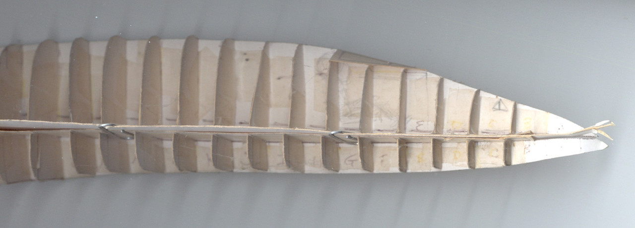 It's the nose area of a rumored hypersonic (?) craft, called the Aurora, as seen in some working drawings or blueprints in a book. I won't bad-mouth the book, because I liked it a lot, and the research they put forth was intriguing enough to make me try to take the blueprint-like drawings they included, and scale up some of the views, so they matched the other views ... at which point I quickly got a lesson I wasn't expecting. I wracked my brains, trying to make one view match the other, once they were all in the same relative scale ... but in the end, I more or less (temporarily, back then) "threw in the towel," and gave up. That is, when I'd done all I could, and it still didn't all add up, I asked a mentor to help me find where I'd gone wrong. He confirmed what I was beginning to suspect: sometimes, published drawings are not correct. I don't mean, certain drawings are not accurate representations of some maybe-imaginary hypersonic (or other kind of) vehicular model. I mean, when the "plan view" drawing someone else drew says the landing gear are located, forward or aft, at a specific spot, longitudinally, and the side view disagrees with that, by three scale feet or more, you have to start asking yourself which of the two drawings is more logical or makes more sense, or whatever. One of them appears to be wrong ... but which one is it? Or are they both in error? I'm not picking on that book -- I'm not even naming it, other than to say the craft's rumored code name -- I'm just saying that when a person gets to the point of making their own working drawings, regularly, and successfully building 3D models (either "real" or digital) you probably ran into several drawing sets that didn't make sense, when you were learning about making working drawings. Sooner or later, just like dealing with plastic kits, you realize that it's not a perfect world, and errors occur; and you have to be ready to get past the sometimes-inevitable hurdles. The guy who was acting in a mentor capacity to me, back then, privately acknowledged that, sometimes, "it's not you" as the interpreter of the drawing set, that is making the mistake. Sometimes, more often than some might think, it's the drawing set's fault; or possibly, the fault of the way it got published. I guess my point in posting that one off-topic-by-subject-matter image, to show that, yes, a person can define the shape of something fairly complex, as the "cracks between solid areas" ... or the way I showed, a bit earlier, with that boat model, where solid forms are being used. It's kind of like choosing to think of it as "positive space" or "negative space" ... with practice, mold-makers can think as easily in "negative" as most people can, in "positive". It's a good skill to have, as a model builder! But it takes some time to get your brain used to thinking that way. So, anyway ... a person has to start really putting the old noggin to work, in terms of imagining "sub-assemblies" making up a whole, and the differences between "positive space" and "negative space" (and 2D versus 3D) before a person on that path can even come up with a "test model" like this one. I made it out of ordinary poster-board; regular everyday household tape; and there's even a few paper clips, holding the upper and lower halves together. (Since they were shaped totally different, I treated them like different models, with a flat plane or area where they joined, at the wing interface -- if that makes sense?) For this scan, I just took that dusty test model off of the wall (where I had stuck it there, with a push pin) and I didn't even dust it off. (Better to show how long ago I made this particular "test model"!?) These days, I tend to go with "solid slices" ... but I didn't always do that. |
|
|
|
Post by wardster on Feb 26, 2021 2:14:45 GMT -5
One last image, before I crash for the night ... it's of that same "Aurora" aircraft, but it's of the back end. 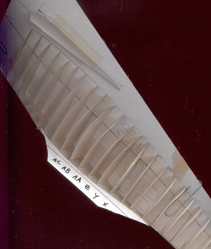 I guess I'm showing this model to say this: the more sections you define, the swoopier the shape can be, and still be easy to "cut out, as if it were individual slices of bread, that when stacked up next to one another, makes a loaf". Another reason I'm posting images like this one, that are (admittedly) off-topic, subject-matter-wise, but are (within the context of what I'm trying to convey, about what I'm doing, and why I'm doing things certain ways) on-topic, techniques-wise ... well, way at the beginning I think I said something about wanting to take something that was essentially hollow (the Hot Wheels "tooned twin mill") and turn it into a solid, via making a mold, and casting it (and some added Kleen Klay) up, in solid form ... and then, essentially, treating it like one of these aircraft test-models, but (sort of?) "in reverse". With these model I was trying to take 2D drawings and convert it into something approaching a 3D object: or the definition of such a thing. With the Hot Wheels car, once I had it in solid form, I could have essentially "cut one slice after another off, and traced it onto paper, and then, repeated that process, until I had a 2D drawing set showing the kinds of cross sectional data, seen here". If this is making anyone's head explode, my apologies for that! It still does it to me, too, at times! |
|
|
|
Post by wardster on Feb 27, 2021 4:12:56 GMT -5
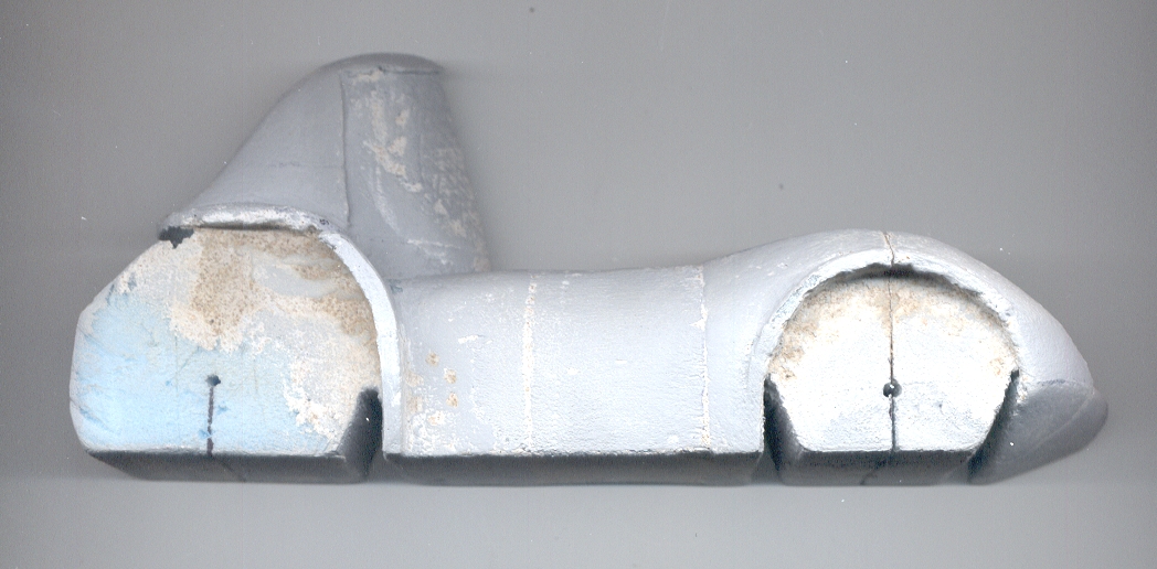  As happened before, the images above are of the same stage of the progress: I just rotated them on my scanner's bed, to get a different "lighting angle" as it were: from above in one image, and from (seemingly) below, in the other image, above. In the image below, I'm showing the "back side". The upper area got sanded down way too much, and is way too small in comparison to my drawings. It just took me a long while to understand the shape (it's more of an "S" along that back line, than a straight, sloping line) and by the time I did understand it better, it was under-sized. (But fix-able.) I'll be adding a quarter inch (or so) thick foam slice, aligned with the vehicle's longitudinal centerline, to make things in that area a bit bigger, as seen from the side: to properly match the drawings. Then I'll play with thicker layers of the stuff I'll mention, below, to fair things in, and to get the multiple shapes that are going on, in and around that area, to "flow" and to do it's complex "thing". 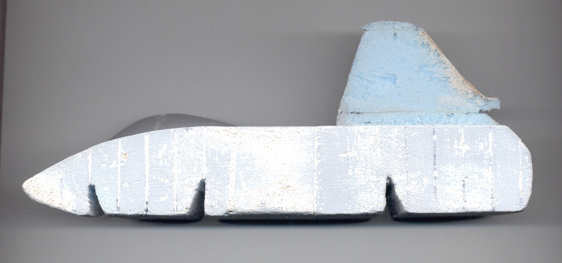 After all that typing, yesterday, my wrists needed "light duty" so I did some gentle body work, here and there, using a filler that is based on what Ed Roth used, and "Spritz by Fritz" used, to create their full-sized show cars. What I used is a mixture of a specific type of plaster ("Presto Patch" by Dap) that I really like for household repairs, and a type of vermiculite (some fine stuff, sold for gardening uses -- but due to the small scale, I ground it even more, using a small portable coffee grinder) and I'm experimenting a bit more than that, with the sculpt-able filler's recipe or formula. With this batch, I added some talc into the mix, to see if it does what I'm hoping it might. (So far, so good.) I've used what I call "P & V" for a few years now: ever since buying a copy of the Spritz By Fritz 2-DVD set, about how to build a fiberglass body at home. Based on what I've read, various artists who create sculpted toys using custom mixtures of wax often use talc as a component of their wax mixtures. For their uses, it alters the working properties of their wax recipes: making it a bit harder, and a bit more able to allow for finer shaped details. I've not used it enough here to comment on the addition of it, other than to say I like it, so far. I'm using a mixture of 50% of the Presto Patch, and 25% each of vermiculite and talc. These are all powders, so it's easy to mix up (relatively) big batches of it, in advance, and store them in dry form. Just add water to what you need, for the task at hand, when you want to fill some minor dings, or re-sculpt bigger areas. I'll cover all this, after it dries, with some MagiKote that I believe I had added some Golden brand artist's gesso, to thicken it. Both of those are white materials, as supplied. Black acrylic paint mixed in with the MagiKote and the Gesso, makes that mixture a gray color. This mix gets brushed on, and it does toughen up the outer surfaces enough to draw on them with a pencil. If you try that on the unaltered foam it dents it, more than marks it. Right now, my stock of Dap brand DryDex spackling isn't usable (it's all dried up, due to old age) but that's another good type of filler, that is safe to use on foams like the ones I'm using here. That's not a powder; it comes ready to apply. It goes on pink, and as it dries, it turns white or off-white. Good for filling big areas. It sands well -- as does the other materials here. |
|
|
|
Post by jffj on Mar 2, 2021 12:16:38 GMT -5
No, I haven't used that, although in my other woodworking projects, I used the MiniWax products frequently. Before I discovered that the Original TiteBond wood glue is sandable, I used to cover and seal my balsa wood pieces with vinyl spackling compound. Easy, quick, and gives a nice smooth surface, but sanding it makes mucho dust. Once I saw the TiteBond was sandable, that's my standard operating procedure now. |
|
|
|
Post by jffj on Mar 2, 2021 12:25:08 GMT -5
Lots of interesting information in your posts Wardster. Just so your hurting wrists are not hurting in vain 😄
We old scratchbuilders find out what works, and what doesn't, and are always open to a fellow scratchers' methods, so thank you Sir for sharing yours.
|
|
|
|
Post by wardster on Mar 3, 2021 2:01:36 GMT -5
Lots of interesting information in your posts Wardster. Just so your hurting wrists are not hurting in vain 😄 We old scratchbuilders find out what works, and what doesn't, and are always open to a fellow scratchers' methods, so thank you Sir for sharing yours. Thanks again, fellow "scratcher"! I think watching your various builds has convinced me I gotta work more balsa wood into this test model's second generation, or whatever I will end up calling the one that comes after this, but before the "real thing". Not much for me to show on this build, at the moment ... I'm experimenting with techniques. Seeing which glues "like" foams, for one thing. I found out that, yes, "Magic Sculpt" (an epoxy-style putty that, I think, was originally for taxidermy?) doesn't mind going over foam, at all ... so I'm planning out how to re-do the rear wheelwell area, in some places, with the MS, where extra strength would be needed. I also tried the "insert an index card" trick, more extensively, but didn't like the results, this time around. Too many slots cut, too close to one another, weakened things enough that it's starting to bug me, so I used some Presto Patch to, well, patch things back up. The biggest problem with that, though, wasn't the test model, it's the miter box. The slots for the blade are far too wide. I cut enough crooked slots that I decided, "No, try something else". Not a set-back on the project: there's other methods I can use. I'd rather not use them, though, if I'm the only one that's likely to want to try that particular tool / technique, down the road. Probably, I'll next be trying to see if I can make up a custom jig to use a contour gauge, to "take off the lines" of this test model. I think I have that part of things at least mostly figured out, but we'll see. Ideally, I can figure it out enough that a common hardware store item, like that, could be used with "normal kit parts"? The not-really-working-much-on-the-actual-model-all-that-often period, over these last few days, paid off in letting me think the sequence through, more thoroughly. I have been breaking the test model down, in my mind, into three sub-assemblies: one being the mid-section and the front end (as seen from the side: the main view, really, for the time being) as one unit; the upper portion, where a figure would go, as the second unit; and the area of the body that surrounds the rear wheel, as the third unit. I was planning on figuring stuff out, in that sequence. I'm now thinking that the second and third should be flipped, sequence-wise. I think getting the wheelwell / fender area sort of mocked in, as a next step, makes more sense than tackling the "roof" area, next. (Or whatever a person wants to call the "part with the human in it" -- passenger compartment? Office for the driver?) In thinking the work flow through, I think the "human's nest" would be easier to work into the whole, if the front part (which I consider already done, or so close to it that I'm not worrying more about it, for now) and the wheelwell was done, first. Those two areas seem like they'd make a better foundation, between them, for the "bits with the human in it". |
|
|
|
Post by Fletch on Mar 3, 2021 17:48:10 GMT -5
Hey Ward,
Still quietly lurking in the backround following the progress. So cool so far!
|
|
|
|
Post by wardster on Mar 3, 2021 17:57:17 GMT -5
Hey Ward, Still quietly lurking in the backround following the progress. So cool so far! Awesomeness, Mister Fletch! Thanks! |
|
|
|
Post by jffj on Mar 4, 2021 13:32:00 GMT -5
Good point Wardster about sequencing.... which still bites me occasionally.
Dang it! I should've done THAT first- and THIS last.... 🤬😂😂
|
|
|
|
Post by wardster on Mar 4, 2021 18:06:26 GMT -5
Good point Wardster about sequencing.... which still bites me occasionally. Dang it! I should've done THAT first- and THIS last.... Yup! I do that, all of the time. Sometimes I'm well into the next whole "test model" before it dawns on me how much easier things would have gone, or how much better the end results would have been (even on an intermediate stage of things) if I had the foresight to "see" that the sequence I was trying to do things, was not optimal; or was, at times, downright problematic! Back a million (or so?) years ago, when I made castings of a homemade turret, to fit the Deal's Wheels dune buggy model (to make a Russian model of the "Swine Hunt" kit) I didn't figure out how I should have made the three part mold, for making those castings, until I'd made probably fifteen or so castings. Then, a better way occurred to me! But it's all okay ... having figured out how to make something with undercuts that severe (it was a hollow part, not a solid one) was a big step for me, in my self-training or problem-solving skills area ... even if I later thought of a way that was arguably better. We all learn more and more, as we go. That's one of the things I like best, about this hobby: the acquisition of many new skills. With that stuff said and out of the way, here's where I'm at on the current "test model" ... 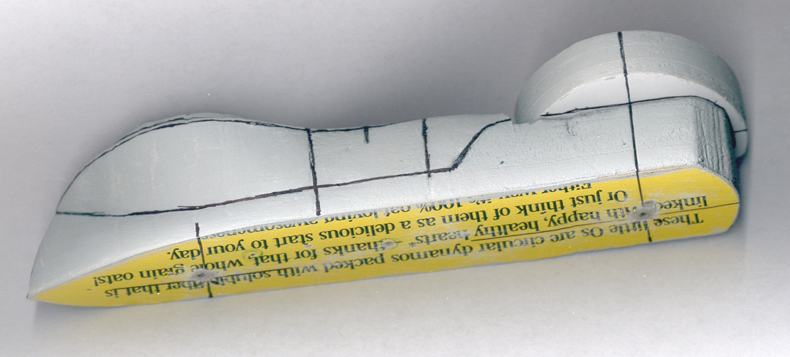  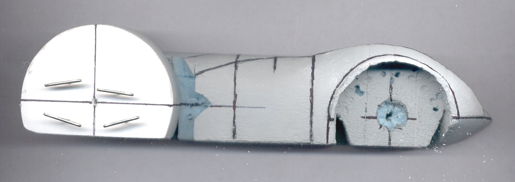 That big thing I added on is both temporary, and isn't what it appears to be: it's not a mock-up of the rear wheel / tire. It's a mock-up of that, PLUS the "negative space" around the tire. I'm still experimenting a bit with the use of Magic Sculpt being added onto pre-shaped foam pieces, to make "stronger" areas here or there, and I wanted the lower part of the wheel well to look "actually round" from about the twelve o'clock position (as viewed from the side) to roughly the three o'clock position, so that big white thingie is supposed to let me accomplish that, via something I think of as "molding in place". Much easier to get something looking round, when the curvature is being set via actually laying against something that IS round. Otherwise, a person gets the "Fllntstone" style of wheels and/or wheel wells, as seen so far with this "test model". A sort of "hidden" part of my methodology is that I'm intentionally not worrying about how certain things will eventually look, until I get past whatever hurdles are right in front of me, at that moment. Perfectly smooth and round wheel wells would not have added much to the visual appearance of this build-up process, until now. But now, without that, I'm being held back. My conscious set of choices to sort of "prioritize" is hard to explain, but I'm ignoring the ugliness that doesn't matter, right now, with the intention of focusing on those areas, as my big moment-to-moment priority, later on. I have a five-step hierarchy I use, which sets my initial priorities as two (very related, even intertwined) things: proportions first, and outlines second. It's almost like that stage of things is one "factory" in itself, and I won't send a model on to the "next factory" (with different kinds of specialists, working there) until the work for "this factory" gets a passing grade. When I get things looking as good and correct as I know how to make them / as they can be, from the strictly-orthographic views (two sides, top and/or bottom, and the two ends) then, and only then, do I start to focus more on "contours". Sequence-wise, I've been on "contours" for a while, with the middle and front of this vehicle, but I'm still piddling away on the proportions and outlines, on the back end. I am not unhappy with that arrangement: a test model's progress sometimes is not evenly distributed. The back end is sort of wearing (slightly) on my nerves, in that it's not as done, yet, as I desire it to be, but I don't fret over it: I'll get there, eventually. Meanwhile, the front end's shaping work seemed to go pretty well, and pretty fast, too ... so if I'm still "at the starting line" or just a hair past that, with the back half, right now, it's no big deal, overall. Normally, I'm trying to interpret 2D references, but this time I am working with a 3D model or reference (the diecast car) and having that physical object to study, sped up the work on the front end, something fierce. But it's not helping much on the back end, in that so many things are going on, in every direction, sometimes in the space of "a millimeter or two or three". Normally, when I have the "proportions and outlines" the way the want them, then, it's like the first "factory" signs off on their work being done, and the test model goes to the "second factory" to get different work done: the contours. With this model, there is a bit of back-and-forth: it's kind of like the guys in both "factories" decided to put the model out into the parking lot, between their two buildings, and they'd both work on it, more or less at the same time. That makes it a bit harder to explain, probably? But with the back half still looking very crude, and the front part mostly shaped, I think you guys can get the idea of what I mean? I hope I'm explaining it well, anyway: both with words, and with the scans. When the imaginary guys from the "second factory" have signed off on the work-so-far (that is, when "contours" are to my liking, across an entire model) and proportions and outlines were previously signed off on, then, and only then, do I send things to the third factory ... which is where different specialists start to work on what I think of as "textures". That's sort of easy to explain, in this group: it's picking all of the surface-level nits one needs to pick, right before the final paint job happens. The surface finish on most vehicular models, at least in our circles, is typically going to be "as smooth as possible" so that step is fairly easy (if repetitive, with all the "putty, sand, repeat" steps). So "factory three" is "post-shaping work" but "pre-paint work" if that way of saying things makes any sense? Paint is the last of the five steps that I focus on -- but on this test model, it won't get a final paint job. The "primer stage" is as far as I need to take a test model, but on a "real model" then yeah, doing the final bodywork and paint is very important. On a test model like this, if there's some minor thumbnail dents in the foam, or errant pencil mark "dents" due to incautious handling or whatever, as long as I can "correct for it" in the stage where I try to make a set of working drawings, the test model, if it still has a few surface level boo-boos, it's okay. As long as I can sort of "draw around it," it won't bother anything. Sometimes I'll do a bit more surface work than others, on a test model. The model's size enters into that decision, and since this one is (by my standards, with some of my other foam-based or MDF-based "sculpting with slices" exercises / models) fairly small, I might do a bit more surface prep work than I might otherwise do, on a test model. But we'll see ... Meanwhile, though, worrying about final paint jobs is pointless, at a stage where the back end is still in the infancy of "figuring out the shapes". If I get antsy, and want to speed things along, I might "take off the lines" on the front end, and start on the final model's front end ... but, again, "we'll see what happens". If it feels like the back end is taking me longer to analyze than I want it to, I might do that. Or I might just keep slogging away on this test model, to complete it first: like it needs to be finished completely, before I allow myself to start a second, possibly-up-sized test model. We'll see. It's still up in the air. So, sequence-wise, here's the (rough) plan, for finishing up this initial test model: "Factory One" is still figuring out what it needs to figure out, on the back (say) third of the vehicle. But has a plan, to get that work done. By focusing on the wheel well area, first, I think things will sort of "speed up" on figuring out the "driver's nest". "Factory Two" is looking for other work to do, while those guys are looking over at the Factory One guys, and shaking their heads. I keep being tempted to "figure out the shape" of that cool Cheetah model, as the Japanese guys completed that resin kit's surfaces, but I know what happens if I divide my work forces, and start work on too many projects. (None get done!) So a certain amount of discipline is being enforced, for me to finish off the back end (factory one's work) and to hand the model to "factory two" so they can figure out the steps they need to do, so that this test model can get passed to Factory Three. One other "this might help, in terms of the sequence" thing I'm thinking, right now, is that I intentionally build things in an "across the grain" fashion -- which will take some explaining. I'm thinking ahead to what will happen when I "take off the lines" after the proportions make sense; the outlines look good; and the contours make sense and look pretty cool. For the actual model, I'm probably going to keep this same size, and I'll be making the front end "sideways" in a sense: laying out the "slices of bread" from one side to the other. The reason for that is, when "faceting and smoothing" work begins, it's WAY easier to see where one "corner of a slice of bread" needs to be trimmed off, to match the next slice of bread's shape. If I was sort of slicing a loaf of (uncut) French Bread, long-ways, the difference from one slice to the next is next to nothing, in a lot of areas, which actually makes shaping work, on the final model, a major "what do these drawings actually mean" set of worries. With the slices rotated ninety degrees (as seen from above or below, and comparing "long ways" to "from one side to the other side" the slices sort of "tell you what to do" ... which will make sense, I hope, anyway, when this all gets to that stage of things. (Best shown, visually, after each "slice of bread" is cut out, and I can just plop them on my scanner, face-down.) But I'm thinking, hopefully logically, about the best sequence for that stage of things, with the back half. I might lay the balsa wood "slices of bread" (in that area, only) sort of "vertically" and "cut from back to front" ... because the shape back there is sort of a modified rectangle, with a bunch of cut-outs (for stuff like the engines, and especially the wheel wells / driver area.) Apologies if anyone's head just exploded? And yes, that's a portion of a Cheerios box, that I glued onto the "insides". I find the cardboard supplied with that particular breakfast cereal makes good template stock, and is tough enough and thick enough for a lot of uses, with goofy projects. A few new-to-me skills got self-taught, over the past few days. One is that (or so initial testing indicates) I can use that MagiKote product, that I'm using sort of as a primer and surface-hardening agent, to stick some things together, too. The three discs I stuck together, to make that "negative space, in positive form" sort of "mold piece" were cut out of foam core sheet, using a special cutter made by, if memory serves, FoamWerks. It dries harder than the paper on the foam core, and harder than the foam itself, but it's still MUCH softer than dried polyurethane glue ... so if I start using it, with success, to stick things like foam pieces to one another, that sanding-related problem I mentioned, before, will be somewhat reduced. Also: I'm experimenting, so with with success, with replacing that small "square" I was using, with something else, to make the index card cross section drawings I had shown, before. Now, instead of making a physical cut into the test model itself, and inserting an index card, and then tracing the cross sections, I'm using a contour gauge as one tool, and a ninety-degree pair of wooden boards, where the ruler (square) used to be. If that makes any sense. Later, I'll show pics of what I mean, but I can put the model into a sort of "ninety degree trough" and then use a hardware store contour gauge to "take off the lines" (as ship and boat builders might say) at any "station" I want to. (But this definitely needs pics, to explain that idea well...) |
|
|
|
Post by wardster on Mar 4, 2021 23:34:07 GMT -5
Not shown (yet) is the diecast car (the HW vehicle that I'm scaling up) in a coat of gray primer. I'm using Mission Model's brand of primer, with their thinner product, and a brush, for that task. It's already making it easier to see details. I'm using it on the one that I showed some days ago, where it's a separate body, that was clayed-up, and is sitting on a random chunk of clear acrylic. The size of the original model was one issue to deal with; the color was another; the sheen was another. Primer is making a dent in all of that. Well, not so much on the tiny size, but that's expected.
|
|
|
|
Post by wardster on Mar 11, 2021 17:31:52 GMT -5
This time, these are not images of my foam model ... these are gridded-off "reference images" I'm studying, of the original diecast vehicle I'm "enlarging" or am "scaling up". Purpose being to understand the true shape, better. 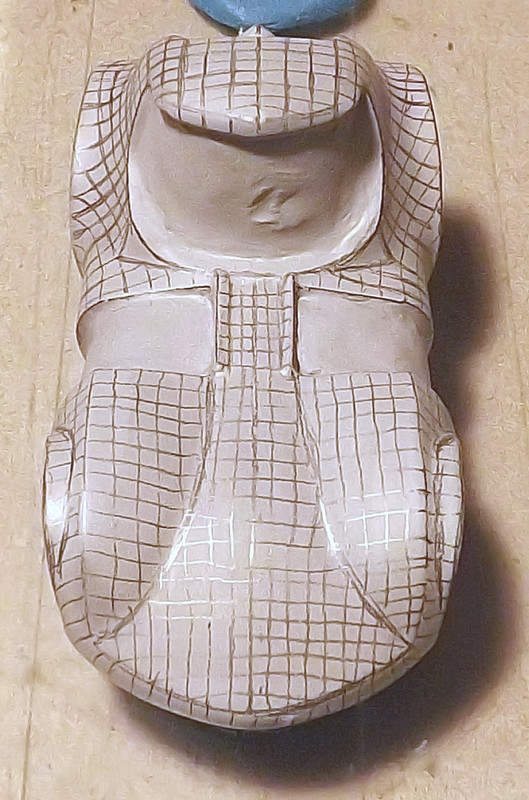 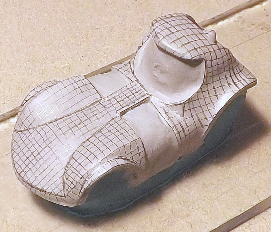 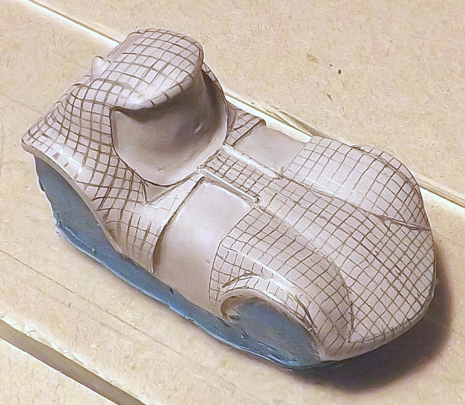 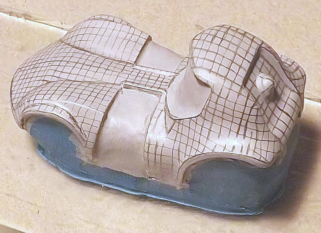 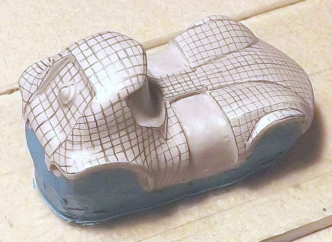 The reason it is gray in color, instead of that sort of "process blue" color, is that I brushed on a few thin coats of a really nifty paint, by Mission Models. Those paints are modern chemistry, in fine form. To get good (and/or the best) results with that brand of paints/primers, you have to use their specific thinner, which is sort of also a hardener (if memory serves: been a while since I read their FAQs / instructions) and you have to follow that company's instructions for application and reduction percentages (or at least come pretty close, number-wise) and what not ... but once you've gotten used to the differences from other paints, it's great stuff to work with. It didn't even care that I was trying to paint it over that Klean Klay, in the areas where I did that! Anyway ... I'm finding out that this "gridding off the real 3D object, for further study" process does not have to be super-ridiculously straight on the individual lines, and it need not be super tight on tolerances, on spacing between the lines, or even how perfectly parallel each set of nearby lines ends up being. Even with some slop, in all of those areas, the idea of holding the real (if tiny) 3D thing in my hand, under that magnifying glass, and studying it as I turn the model to various other angles, or compound angles, or whatever, is teaching me about a lot of subtle nuances -- as well as the larger curvatures, shapes, and so on. Stuff I probably would have missed, or maybe misinterpreted, without doing a process like this one. I hadn't "caught" those triangles at the base of the front windshield, for instance, until I did that process. Then, under magnification, the primed body showed a huge "cliff" or "drop off" at that point on the model. Now that I know it's there, I can "see it" on the blue car, too. When I gridded the small diecast car body off, it was basically "by eye" with a short, sharp pencil. (A pencil that would let me fit it under a lighted magnifying glass, without hitting the glass itself with the back of the pencil, all the time. That gets really annoying, and kills my concentration, when I'm doing work like this, and hear "tink!" and get my hand bumped, from an overly-long pencil.) Anyway, I first hit any obvious "seam lines" or sharp areas of two shapes, intersecting, at various points / areas on the model. And I looked for any high points, around the body, too: so I started by finding the "concave" and "convex" interface or "lines change here" areas. Found things like those modified-shape triangles, next; sometimes by spotting subtle hints at where the factory's mold lines were. When I had all that drawn up, that had given me enough practice to tackle the actual "gridding off" process. It may be obvious (?) already, what my intent was, but in case it's not clear: the idea behind adding those lines is to have them sort of "bend" when I'm rotating the 3D model, and studying it. I tried to make them reasonably straight and reasonably parallel to one another (if they're going in the same basic direction, that is) as seen from the "orthographic" angles: looking straight down as viewed from above the model; or looking straight at the model but from a viewing point the side, and so on. Turning the 3D object from that view, to a "3/4 view" reveals much. Sometimes what gets revealed is that what looks like a heavily curving area, is actually a lot more "flat" than it first appears. Sometimes, the sudden changes are at least as pronounced as it first appeared, or maybe more so. In a sense, I'm sort of studying "proportions and outlines," again, but on a smaller sub-part of the whole 3D car body. |
|
|
|
Post by wardster on Mar 11, 2021 18:36:57 GMT -5
Some visual stuff, to show some subtle things I'm picking up on, as I stare at the 3D diecast car, in its "gridded off" state: 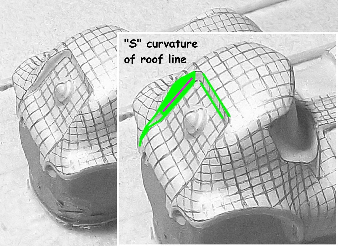 Picture above: this confirms what took me some time to see, earlier in this analytical project: that there is a subtle (maybe one millimeter?) bump in the roof line, as viewed from the side. Thinking it was a straight line, originally, in 2D form before I worked on my foam model, didn't work out at all. I finally noticed it's actually an "S-curve" not a straight, flat line at all.  Picture above: from point A to point B, that's a flat and straight line (as shown here). But note that the sharp line of the actual hood area, isn't flat: it's two downwards sloping lines, with a high point in the middle area. Sort of an upside down "V" shape. Or to put it another way: on the small diecast car, that area slopes sharply away, from the center. You can see more of the engine's back sides, due to that somewhat-unexpected design decision. I had to actually study the non-tooned diecasts of that same basic subject, to see it's a decision more or less reflecting what the 1960s diecast had done. (I'm judging that based on a 2011 "Boulevard" casting, with improved details, like rubber tires, of the Twin Mill car.) But on the Twin Mill III, which I have several copies of, it's something else: that area of the car shows a continuation of the fender lines, as seen from the front wheel's vertical centerline, going backwards. So the 1960s diecast car and the tooned one "agree" on that area of the shape, but the Twin Mill III does not. On my foam model, I've decided I'm not going to do what the small (tooned) diecast car shows, in that area. I had decided, a bit ago on this project, that I wanted to sort of "fill in those two big blank spots" with my foam "half model" to show a continous shape, in that area. That way, with the drawing set, later on, if I wanted two engines, just cut stuff away, but if I wanted one (centered) engine, I could do that, too. So in this case me not following what the tooned model did, is not an "error" (as I see it) as much of it simply being an area on the foam test model that I want to change, for reasons that don't apply to the diecast tooned car. I'm not making changes because I "disagree with" the design decisions I'm seeing: I'm just throwing an extra "what if?" challenge at myself, by asking "what would the negative space look like, if it was not just an empty hole, in those two big areas"? EDIT: On second thought, I think I'm going to include that "sloping droop" or whatever a person might call it, on my foam test model. Experimenting with flowing shapes, and making them all "line up" and "do cool things" is part of the point, after all. I say that after a few minutes of cutting the foam model with an X-acto knife (#11 blade) and some sanding-stick smoothing. |
|
|
|
Post by sharp on Mar 11, 2021 22:14:48 GMT -5
Lots of work going into this! Looks great so far!
|
|
|
|
Post by wardster on Mar 12, 2021 0:47:32 GMT -5
Lots of work going into this! Looks great so far! Thanks, man! Much appreciated, Mister Sharp! A heads-up for later: I have a few actual "in progress" photos, stacking up in the queue, now that I (finally) got some batteries for my camera. (I gave up on local stores stocking rechargeable batteries, and just got the one-use-only "normal" kind.) Not yet shown: I'm working on that back end's wheel well arc, using Magic Sculpt; and (in other areas of the model) I am doing multiple rounds of "putty, sand, repeat" (but using that mixture of 50% Presto Patch, plus 25% finely-ground vermiculite, plus 25% talc) forward of that area. I'm really liking how both of those materials are working out, for what I'm attempting to do with them ... but I'll get caught back up on photos, before too long. I might have said this already, but in case I didn't: my models of this type ("test models," in general) tend to "look like (poop), right up until they don't". In a few areas, it's already where I want it, and improving even beyond that. Others ... "not yet". For what it's worth: as I was working on the latest refinements to the body's shape / detailing, earlier tonight, after the uploads I did earlier, I was thinking that doing stuff like this probably takes two traits or qualities, mainly: the courage to start a project that you're not fully comfortable with, or don't yet understand every step you'll need to accomplish, and giving yourself permission to not get it right, right away -- but to keep plugging away at getting there, in little steps, if need be. |
|


