|
|
Post by wardster on Feb 15, 2021 19:45:56 GMT -5
I'm not quite ready to make an official "Racer" contest entry thread, yet, but if I do, it'll probably be based on this drawing ... 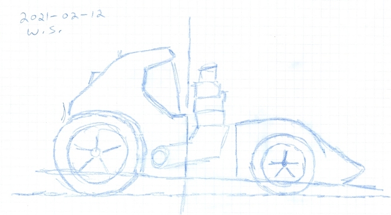 ... with that drawing being an up-scaled or enlarged image I created, based on a sort of "tracing" of the tooned version of the Hot Wheels "Twin Mill" release, that PlastiMatic showed images of, over in the diecasts section of these boards. Right now, I am not farther along than a series of fairly raw / initial "working drawings" ... and even if I was, my camera's rechargeable batteries (grrr!) refuse to stay charged up for long enough to take pictures of anything. So I'll have to get past some initial hassles, camera-wise, and also make more progress, before I post any actual "work in progress" photos. In the meantime, here's the inspirational photos that Plastimatic had made, showing the Hot Wheels scale version of that vehicle: car-toons.proboards.com/post/17660/threadWhen I can take photos, and upload them, I'll start explaining more about how I got to where I had a scaled-up drawing ... but the short "teaser" explanation, for right now, is that I learned that an ordinary pen can write on the sticky side of packaging tape, without any huge problems; so I stuck some of that onto a piece of a cereal box's cardboard (like the cardboard was a wooden frame, around a picture hanging up on someone's wall) and I traced the Hot Wheels car's side view, that way. I did the top view, that way, too ... but I'll save any other pictures for later. For right now, I'm merely sort of "dipping my toes into the water" and sort of "pushing myself to get a project started, and (hopefully) completed". It's been too long since I got very far with any of the more detailed, multi-step, lots-of-analytical-work-first projects. Fingers crossed ... |
|
|
|
Post by jcon on Feb 15, 2021 20:36:25 GMT -5
Looks cool!!!
|
|
|
|
Post by wardster on Feb 16, 2021 22:07:06 GMT -5
Thanks for the "likes" and kind words, JCON and JFFJ! Here's another image, showing the (slight) progress so far: from rough 2D shape, to (very) rough 3D shape. This is a scan, not a photograph, which is why it probably looks pretty weird. I'm trying to show that I have the rough shape cut out, from one viewing angle (from the side or "profile" or "elevation" view -- different people use different names for it) but that I'd need to add data that I glean from the "plan view" drawings, and once I have that cut into this "foundation foam" it's "round stuff off, on corners and such" ... following what the tiny 1/64 scale toon car tells me to do, shape-wise. Some nerdiness that is not super-obvious, just from glancing at the image below might include the idea that I drilled holes, straight down (towards the vehicle's center, and parallel to the "ground," with the vehicle's centerline flat on the table) with a drill press, on any of the "lines I know I'm going to lose, when 3D shaping begins". Stuff like what the side view of the windshield looks like. The idea there is they retain their position, as seen from the side view, if you drill deep enough.) 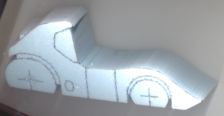 Overall explanation of the madness that's going on: This is the first steps working towards figuring out what the actual 3D shape will look like. In one of my other areas of interest, I studied what ship modelers did, to either "take off the lines" of a real boat or ship, and transfer that data into model ship form; or to go from a scale replica up to something like a real boat. In other words, this is going to be the first "test model" (probably of several?) that lets me figure out all the details I will need to figure out, to be able to make a set of working drawings with enough detail (cross sections, as well as profile (side) view drawings, and plan (top or bottom) view drawings; plus, later, the end views). A lot of that work-to-come can't easily be photographed, hence my explaining with words. EDIT: One thing I should mention is that when I'm doing this sort of nerdiness, early on, in a project like this, I'm focusing on only half of the model. Why? It cuts time way down, and frustration way down, to get any "mirror image" object figured out, only once. The other side, when I sort of "do a 3D tracing" (if that way of saying things makes sense?) is easy: just flip the 2D drawings over. So by only focusing on half of a two-part symmetrical object, you eliminate a lot of headaches and lost time. As for the material I'm using, here, it's "foundation insulation" which is about 1.5 inches thick in this case. I have oodles of it left over from other projects, and I'm cheap, so I'll work my way up to more "expensive" materials as I get closer to "the truth". But right now, using ultra-cheap materials (this stuff is sold in 4-foot by 8-foot sheets, at big hardware stores) encourages me to be aggressive on shaping things, but if I was using stuff that I had less of, or that was significantly more expensive, I'd be all Cringe City at doing really sloppy-looking cuts-and-pastes ... so, I'm only doing half, and am only "roughing it out," now: this won't be the final model, by any means. I only need this one to tell me enough to have more confidence for the next one. That was sort of the "how" of my future plans for this project ... and here's more of the "why" of me doing things that way: First off, it works. I've done it this way on a lot of other models, that I took to completion, and was happy with them. I'm used to working from things like 2D screen-grabs, or photos, without ever seeing the "real thing" or being able to hold it in my hands, as I make a 3D copy. This time, I'm working from both 2D drawings that I made, off of the real 3D thing, plus I have the "real thing" in 3D form, as well. So I can cut some corners (literally and figuratively) ... but I'll get to all that, later on. I plan to (by many people's standards) really nerd out on this stage of the game ... but there's a method to that madness. To explain it as simply as I can ... a lot of methods will get a 3D model made, but what if someone told you, "That's great, but I want three more just like it, except one has to be twice the size, and the others are also not going to be the original's size?" In such a case, without some REALLY detailed drawings to work from (lots of cross sections, especially) it's like starting over, for each new model. With a great drawing set, it's easy to scale things up; or scale them down; or to make significant changes. The end game is that while this way that I'm using seems really slow, up front, the second time a person builds one of these items, all that's needed is the drawing set, some sheets of material (balsa wood, for instance, or foam) and some patience in cutting out many "slices of bread" that a person sort of "glues into one big loaf" and then, does some minor smoothing work. Once upon a time, another board member saw some of the sci-fi (?) nerdiness I was doing, and compared it to being a "human 3D printer". That comment will likely make more sense, when I get to the second, more refined test model ... and beyond it. Anyway ... more later. I'll try to work on getting my camera's batteries replaced, so the next steps will be easier to show. |
|
|
|
Post by wardster on Feb 16, 2021 23:06:48 GMT -5
This next scan (shown in a "straight on" or "orthographic" view, from the side) shows removing the upper roof area, so I don't have to do any complicated "figuring outing" on the next step, which will be defining the shape of the lower edge of the front windshield. That step is going to be way easier to do, with that part treated as if it was a completely separate subassembly. 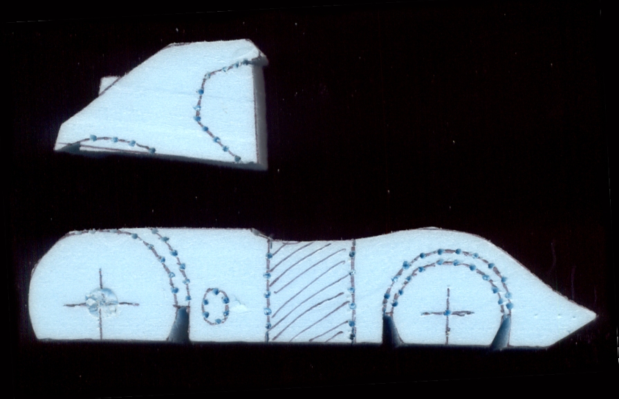 I'll likely do something similar (as seen from above) when I refine sort of the "hood's center area" versus the wheel arches ... but one step at a time, right? EDIT: Not shown, but done right after the step shown, above -- I cut the upper roof line off, as well. By doing that, I can flip the "windshield glass piece" over, by ninety degrees, and start defining what that (important, on this car!) shape looks like, from both the lower and upper portions. That's a critical thing to do, with this model, since if I get that looking wrong, it won't much matter what else I do. It's a pretty iconic "top view" on both the non-tooned and tooned version of that "original". |
|
|
|
Post by jcon on Feb 17, 2021 1:27:46 GMT -5
Lots of prep work will save time later for sure!!! Good job!!!
|
|
|
|
Post by wardster on Feb 17, 2021 2:40:43 GMT -5
Lots of prep work will save time later for sure!!! Good job!!! Thanks, man! And yeah ... it surely does! I did manage to get more done on that "test model" or "half hull model" (to use the ship-building term) tonight, but won't be ready to show much more until later. It's to the point (at least in the "back half" or "glass area") where photos rather than scans is going to be necessary. Video would work better, for explaining some stuff, but still photos and some words will have to do. |
|
|
|
Post by wardster on Feb 17, 2021 14:19:39 GMT -5
Just so it's more clear, as things progress: one "oops moment" on the explanations above, was when I said that slice of scrap foundation insulation foam I am using was 1.5 inches thick. That's what it was supposed to be; but as shown, it's actually 2.0 inches thick. I later cut off half an inch, along the longitudinal (vertical) center-line area, to make it all the correct width.
I did that, mind you, after some confusion when I saw that nothing was lining up, in terms of my layout marks in the window area, as seen from above, when I tried to lay out my next cutting / shaping marks, as seen from that angle. Then it dawned on me that I had grabbed a piece that was MORE than thick enough, but I had not cut it to final size.
Oh well. I told myself I would try hard to not over-think this test model, any more than I have to, and I'm doing so well at not over-thinking, that I'm apparently under-thinking. But I caught the error, and I fixed it. No biggie.
|
|
|
|
Post by wardster on Feb 17, 2021 20:12:01 GMT -5
For reference, here's what the small-scale vehicle body looks like, that I'm trying to scale up: 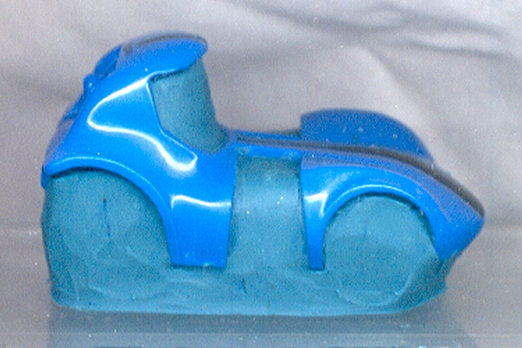 As seen, it's a Hot Wheels Twin Mill (tooned) car, that was taken apart, and then stuck (using some "Klean Klay") onto a scrap of acrylic sheet. I wanted to be able to see what the body's actual shape was, without all the "sub-assemblies" (wheels, tires, engines, etc.) in the way. The engines, in particular, are quite the visual distraction, when you're trying to "see past them". Originally, my plan was to make a mold of the actual Hot Wheels body, as seen here; and to cast up a "solid copy" (instead of a "hollow original") with the plan of cutting up that solid casting, so I could trace around it, precisely. But then I looked inside my wallet, and said "Yikes!" at the idea of all the casting rubber and resin that method would take ... so, we're doing it "this way" that I've already described. But if this was some NASA-funded project, I'd be using more precise methodology, etc. My original worry was that if something (for instance, like the front hood area) is approximately one centimeter (10 millimeters) high, and my methods are going to be off by, say, two millimeters, that's "off by twenty percent". Even if they were only off by one millimeter, that's still 90% correct and 10% wrong. So, this way, I'm kind of asking myself "How well are your eyeballs calibrated?" ... and even if their unaided state isn't perfect, "cheating" by scanning the body in, and having the lighting showing me where most of the twists and turns are, on an enlarged view of the object ... that's all useful to have, too. So, in hindsight, I'm kind of glad I couldn't easily afford to do things the much more precise, and much more costly way. This limitation forces me to do things in ways that I haven't yet done them -- forcing me to learn new methods, and ways around things, for the next time I'm doing something silly, and the conditions are less than ideal. And the reality is, once I have documented the "actual" body shape, as closely as I can manage to with what I'm working with, in terms of resources, knowledge, skills, etc., knowing me, I'm very likely to make some alterations to it, anyway, before I make the final body, for the final model. While it's all still "raw data" that is still in 2D (and/or was enlarged and made into a 3D form, that can be measured or traced or whatever a person will call the later steps) ... well, race vehicles always get modded, anyway. |
|
|
|
Post by wardster on Feb 17, 2021 20:56:48 GMT -5
Another image of recent work on the foam "half hull model" ... which I hope makes sense to viewers? This is a view of the foam model, as seen from above, but with the upper areas cut completely off. (That part is sitting, elsewhere, now. My methods, in these "early daze" images, involve a lot of "cutting things out of my way, to make certain steps easier.) 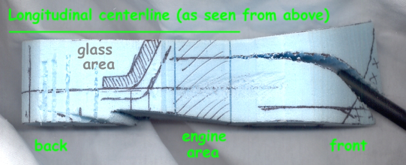 What's going on in this latest image is I'm showing that I made a cut, as seen from above, in the front hood area. Why? It'll be easier to shape things if the toon's very distinct line, between the (relatively) flat center area of the hood, and the outer fenders (which, on the toon's body are much more rounded, and peaked, and flowing, and fairly complex-shaped in cross sections) is marked in a way that I can't miss it. I can treat the center of the hood as one sub-assembly; and then, take cues from that, as to how low the fender area's "dip" should go. I'm "marking my territory," as it were, with a physical cut, down the hood. I'll probably cut that center of the hood area off, completely, a bit later, so I can shape (with a sanding stick) the fenders more easily, with that other part of the model not in my way ... but for this image, I wanted to visually show it "split". (I shoved a random tube into the split, to widen it for this scan, otherwise, the cut would probably look like a pen marking?) Areas like the bottom of the glass, and that split that I just discussed, are great areas for "getting into the ballpark" better. I try to take advantage of the "Rosetta Stone" effect they can give a person, who is looking to figure out what swoopy shapes go where, and how all of the convex and concave curvatures match up, and where. Use any "cheat lines" you find on the original! Another reason I'm doing this, to get closer to where the final shape needs to be, is that I used a tool for capturing contours (a hardware store item) on things like wall molding, down the original model's body centerline. It's not shown here but I have that hood's mid-point marked off, on the rest of my drawing set. Making that cut easier for me to imagine, and to get as precisely in the right place as I'm going to. Much better, using tools like that, than trying to just eyeball everything. To make the actual cut, I used a not-plugged-in and not-powered-on scroll saw, with a round-cross-section, spiral-cut blade in it. The foam is so delicate, and the saw vibrates so violently (if it's plugged in / powered on), that it was easier / safer to just push the upper arm on the saw up and down with one hand, while holding the foam model with the other. I got a much more precise cut, in that delicate material, that way. The foam isn't really made for this kind of work, so anything a person can do, to be more delicate, is a good move. |
|
|
|
Post by sharp on Feb 17, 2021 22:21:00 GMT -5
Very cool idea!
|
|
|
|
Post by jcon on Feb 18, 2021 11:54:30 GMT -5
Wow!!!
|
|
|
|
Post by wardster on Feb 18, 2021 19:29:56 GMT -5
More images ... but I'm going to "go lite'r" with words, this time around. (My wrists are acting up. Darn my carpal tunnel syndrome, for slowing me down on hobby stuff!) 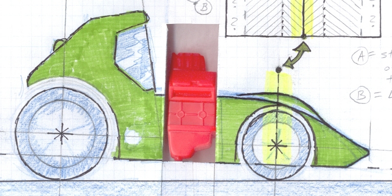 That's a Deal's Wheels engine (out of the Baron's Fokker "Funfdecker" aircraft caricature kit) sitting in a cut-out portion of the drawing. It may not be the actual engine I use: I just had it, and wanted to show that my intent is to make the physical 3D "test model" in scale with those kits. 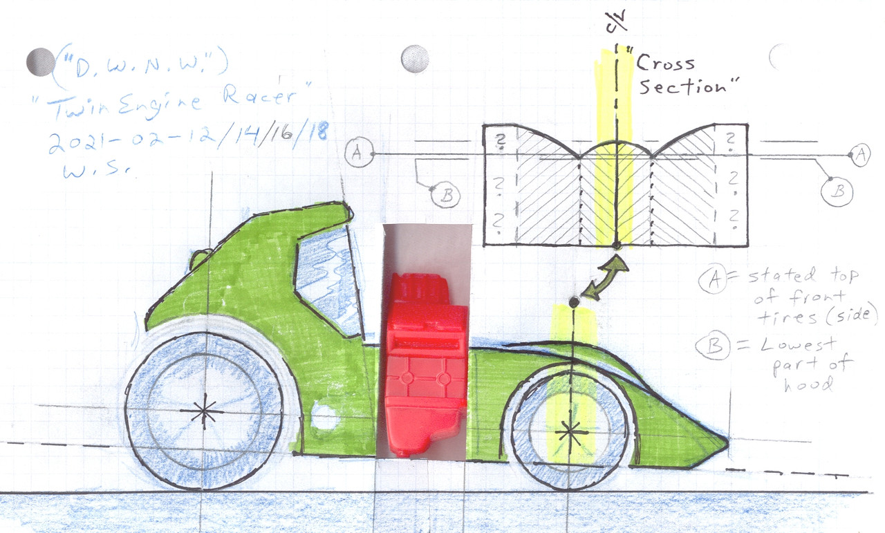 The cross section drawing attempts to explain what I was saying, before, about how the hood on the Hot Wheels car has fenders that stick up way higher (towards the outboard edges) than the center of the hood sticks up. In cross section, it's sort of shaped like a "W" between those high points on the fenders, I haven't figured out any more than that, cross-section-wise yet. To figure that much out: I cut that part off, that I talked about before, and I did some preliminary 3D contouring work with a razor saw and a sanding stick, in that area of the model (and forward of it; but only in the shaded or "no question mark" areas) ... if any of those words make sense? Still lacking camera batteries, for the time being; so I'm making images via scanning, for now. |
|
|
|
Post by wardster on Feb 18, 2021 20:04:35 GMT -5
To give a better idea of how much (or how little?) this "test model" is "in scale with Deal's Wheels" kits, here's an image that shows the foam "half-hull model" sitting on my scanner, next to the (unmodified) body of a DW "Go-Mad Nomad" kit. 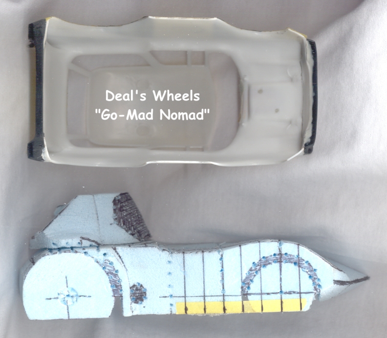 |
|
|
|
Post by wardster on Feb 18, 2021 22:27:10 GMT -5
What I'm trying to show, with the next two images, may not be clear? And is going to be very hard for me to explain, in words, too. The gist of it is this: as seen from above, if you've laid down nice and straight lines (and I'm not saying mine are perfect, by any means!) it will keep looking pretty straight (but maybe not perfectly straight?) as seen from directly above. I laid these lines down, following a laser's beam, with a Sharpie marker. The laser is in a custom wooden holder I made, to lay out "datum" or reference lines on much larger models. So even being off by a little bit, shows up here as "wavy lines" whereas on a larger model, it would not be as obvious that the "tracing the laser beam" portion of what I'm doing, is a bit sloppy. (It is a bit more difficult than it sounds to "trace" the red light beam, since the Sharpie's line, where you're drawing it, sort of "becomes invisible" while the beam is over it. So if you're tracing it very well, you won't see where the line is showing up. I wandered off, a bit, here or there, but for the most part, these layout or "datum" or reference lines are SUPPOSED to be straight! So, anyway, here's the "looks mostly straight, as seen from directly above" picture. (But note that the actual "window glass" and "passenger compartment roof" piece is sitting off, somewhere else: I'm focusing on only the area below the glass -- a classic case of being careful to pick your battles well. The glass is going to be a pain to really "nail" ... so, that's "later".) 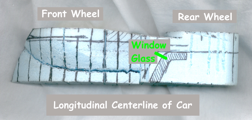 And here's one as seen from a compound angle -- sort of like I had the real full sized car out in my yard or something, and I was looking down at the real full sized car, while standing a few steps up, on a ladder. 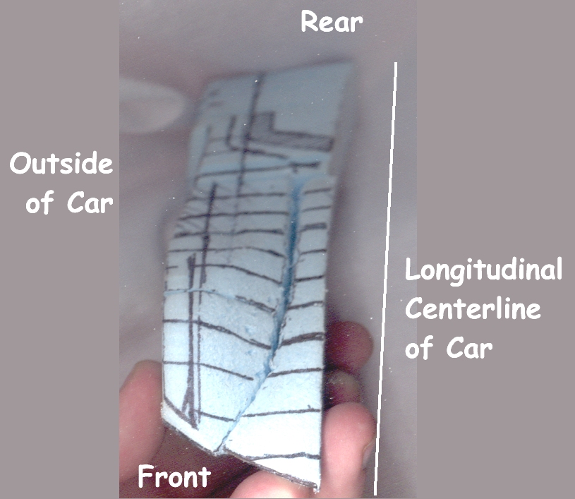 This was the best angle the scanner wanted to give me, but it is not a perfect image. (Sorry!) I'll eventually get camera batteries, and can re-do some shots ... or I'll show the car, with layout-lines like here, but after I shape it more, and put some gesso on it. My main point here, with these two photos, is that those "mostly straight" lines (as seen from above) are suddenly able to "bend around the shape," if seen from a different view. Usually I'm trying to use that trick, with the real "test model" to see if shapes are "fair" -- that is, smoothly curving, without any lumps and bumps, or as some ship modelers call it, "humps and hollows". If nothing I said, just now, made any sense ... sorry! ... but hopefully, as things progress, you will see other images with those "at ninety degrees" cross section lines drawn on it, and you'll have some idea of why I'm using them: it helps me to see if my shapes are coming out okay. In a weird sense, these lines are (sort of!) like a "guide coat" when a person is applying body filler, and they're sanding a compound curve down. A sprayed-on "guide coat" would find any low spots, that could / should be filled in, as shaping work progresses. This is sort of the "very coarse" version of that: I'm looking for BIG bumps, and BIG "valleys" so I can smooth them. I'm also twisting and turning the model in my hands, and staring at it from all kinds of angles, as I work on trying to match the various concave and convex curves, and subtle transitions, etc. With much larger models, each one of these "stripes" that I'm creating, visually, with pen lines, would probably (if the shape was really a pain to match up) be in alternating foam colors: pink, then blue, then pink, then blue, etc. -- and that makes it super easy to see any weirdnesses. Later, these pen lines will likely be placed where seams are, between something like slices of balsa wood ... so there's another "method to my (apparent) madness" with these pen lines. So I drew the first one right at the centerline of the front wheel, since that's where the "peak of the hill" is the highest, on the outer fender portions. That way, on either side of that (going back or going forward, I mean) one gluing face (or visible seam or edge) of each "slice of bread" is perfectly defined by a cross section drawing. Starting somewhere else makes things less clear ... so on that, I'm saying "I'm premeditating future steps". |
|
|
|
Post by wardster on Feb 19, 2021 1:01:35 GMT -5
The initial shaping on the front end is more or less complete. (For now.) I'll focus on the back end, next. With stuff like this, it's best to "put it away for a while" ... or ignore one portion, while working on another. Come back later, with "fresh eyes" and see if you can spot anything amiss. For now, this is as good as I'm going to make the shape of the front portion of this test model. 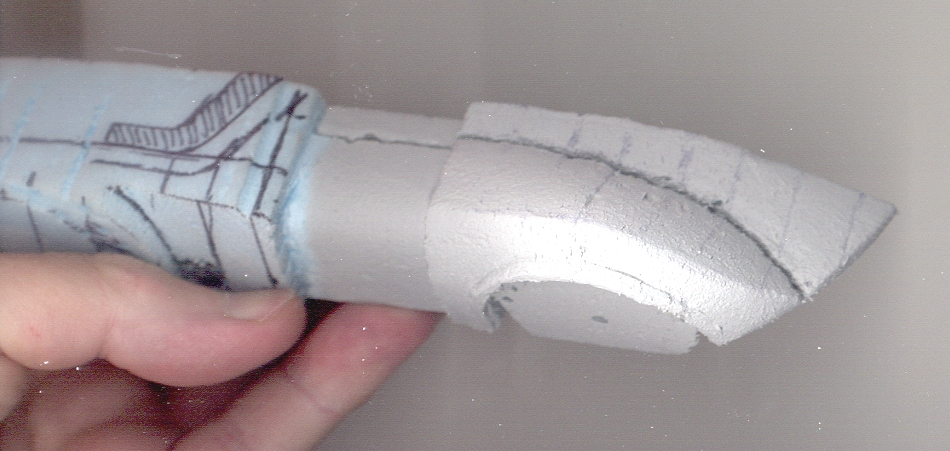 |
|
